¶ RS485 Biasing
A recent prototype of a RS485 VFD interface was working intermittently. With some VFDs, it would sometimes work and sometimes fail, while other VFDs would not work at all. The problem turned out to be insufficient bias on the RS485 A/B data lines. https://www.ti.com/lit/an/slyt324/slyt324.pdf explains RS485 biasing.
¶ Old circuit
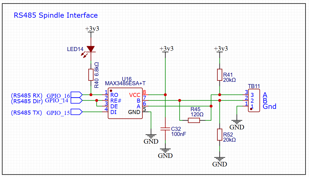
The bias - i.e. the voltage difference between RS485 A and B - is set by R41, R45, and R52, in combination with the external 120 ohm termination resistor in parallel with R52. The effective resistance of R52 in parallel with the external termination resistor is 120/2 = 60 ohms. The total series resistance in that path is 40.06K with 3.3V across it, so the current is 3.3/40060 or about 82 uA. The bias voltage from A to B is 60 ohms times 82 uA - about 5 mV. For reliable operation with legacy RS485 transceivers, the bias voltage needs to be at least 200 mV.
¶ RS485 waveforms with old circuit connected to YL620 VFD
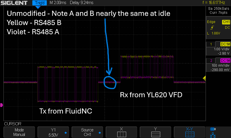
In this scope trace, the RS485 waveforms (A - yellow and B - violet) are overlaid, showing that, during the idle time between Tx and Rx, their voltages are nearly identical.
¶ UART Rx waveform with old circuit connected to YL620 VFD
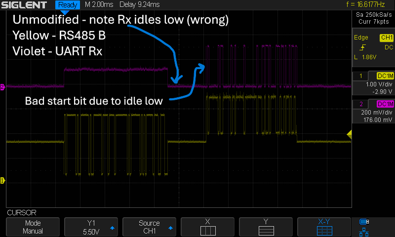
The violet trace is the UART Rx signal from the RO pin of the MAX3485 chip. During the idle period between the initial Tx burst and the Rx response from the VFD, the Rx line is idling at the low voltage state. That is incorrect; a TTL UART signal is supposed to idle at high. When the Rx burst comes in from the VFD, the UART Rx transitions to high, but that does not represent a valid UART start bit. A start bit is supposed to be a transition from high to low. Therefore the UART in the ESP32 microcontroller cannot recognize the correct first character; that character and subsequent ones are garbled.
The MAX3485 chip datasheet says "The receiver input has a fail-safe feature that guarantees a logic-high output if both inputs are open circuit.". As shown here, that feature is not sufficient to guarantee system operation in this setup.
¶ Corrected circuit
According to the formulas given in https://www.ti.com/lit/an/slyt324/slyt324.pdf, the resistor values should be 392 ohms for R41 and R52, and 137 ohms for R45. For a quick test, I put 383 ohm resistors across the existing R41 and R52. With R45 at 120 ohms and the additional 120 ohm termination resistor at the other end, the calculated bias voltage is 244 mV.
¶ RS485 waveforms with corrected circuit
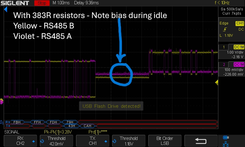
Note that RS485-A is above RS485-B during idle.
¶ UART Rx waveform with corrected circuit
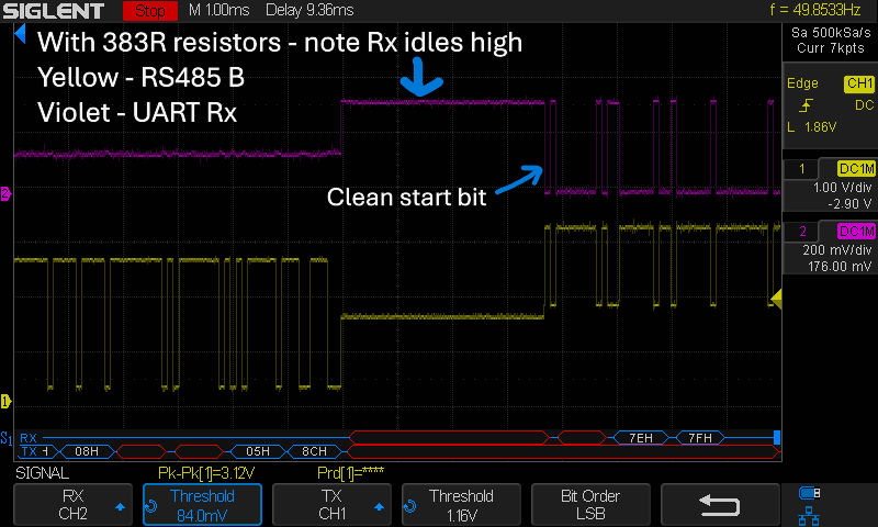
With the bias during idle, the UART Rx line is at the high state during idle, so the UART can detect the start bit and frame the characters correctly.
¶ Results
Without the modification, FluidNC was unable to communicate with the YL620 VFD, giving "unresponsive" and "Queue Full" error messages. With the modification, it works.