¶ ESP32 Reset Challenges
¶ Hardware Behavior
Most ESP32 modules and boards implement a reset circuit that looks like this.
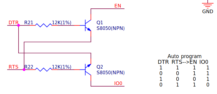
DTR and RTS are controlled by a USB Serial chip like CP2102 or CH340. When DTR or RTS is “true” with respect to the software API on the host, the corresponding hardware line is low.
EN and IO0 go to the ESP32 chip. They usually have pullup resistors, and EN usually has a capacitor to ground. When EN is low, the ESP32 is held in reset; its code begins execution when EN goes from low to high. If IO0 is high when EN goes high, the normal application code is executed. If IO0 is low when EN goes high, the ESP32 runs the serial bootloader - “download mode” - allowing you to rewrite the FLASH contents with new code.
It would be possible to connect DTR directly to IO0 and RTS directly to EN, avoiding the cross-coupled transistor logic. My hypothesis for why Espressif did not do that goes all the way back to the ESP8266, which was often used in a very-low-pincount “ESP01” module format. Using the cross-coupled logic permits you to control reset and download mode, while still allowing IO0 to be used later by application code. When DTR and RTS are in the same state - the normal case in most scenarios - IO0 is not driven by the transistor logic, so it can be used for other purposes. IO0 or EN is driven only when RTS and DTR differ.
The cross-coupled logic is tricky Normal reset is relatively simple. Assuming RTS and DTR are either both 0 or both 1, setting RTS to 0 and DTR to 1 will drive EN to 0, then setting both RTS and DTR to the same value - either both 0 or both 1 - will release EN to restart the ESP32. Reset to download mode is a little trickier. To enter download mode, EN must go high while IO0 is already low - implying that they must both be low just before EN goes high. But there is no RTS/DTR state where both EN and IO0 are low. This conundrum is resolved by a capacitor on the EN signal. When EN is released from its driven-to-0 state, the capacitor takes some time to charge, so the ESP32 does not see the low-to-high transition immediately. Starting from the state DTR=1.RTS=0, EN is low and IO0 is high. If you then transition directly to DTR=0,RTS=1, IO0 goes low immediately and EN starts to rise, but the ESP32 does not see the EN transition immediately, so it registers IO0 as low when the EN transition finally happens.
¶ Capacitor Values
The dev kit modules generally have (2) 0.1uF capacitors from the EN pin to ground. One is near the reset button and one is near the EN pin on the ESP32 module. When in doubt use these values.
¶ Surprise Behavior
When both RTS and DTR are high, the emitters and bases of both Q1 and Q2 are at the same voltage (3.3V), so it is tempting to think that the transistors are turned off. That is not always true. If you start with the state DTR high RTS low so that EN is low, with its capacitor discharged, then drive RTS high, Q1 goes into “reverse active” or “inverted” mode, with the collector voltage lower than the base voltage. In effect, its collector and emitter switch roles! That causes the EN capacitor to charge through the reverse-active Q1 instead of through the external 10K pullup resistor. The capacitor voltage rises quickly to about 2.7V before the transistor starts to turn off. This only happens when DTR is high; when DTR is low the base voltage is less than or equal to the collector voltage, Q1 is off, and the capacitor charges slowly through the external pullup resistor.
¶ Software Considerations
There are some complications at the host software end. There are many layers between the application software that wishes to control the RTS and DTR lines and the actual lines on the ESP32 board. The application code is probably using a serial library, which in turn is going through an OS API, which then goes through a driver for a USB-Serial chip, which then sends commands to a USB host interface chip, which sends USB packets over the USB bus to be interpreted by the USB serial chip on the ESP32 board, which finally drives the RTS and DTR lines. The timing and detailed behavior of those components is often difficult to know and impossible to control. In particular, it is not always possible to change the states of RTS and DTR simultaneously. If the application code asks to change RTS/DTR from 01 to 10, some element in the path might choose to - or be forced to - change one then the other some time later. It can be different depending on which OS you are using, which libraries you are using on top of that OS, and which USB-Serial chip (and its associated driver) is present.
To add one more layer of confusion when thinking about the situation, the assertion state for the hardware lines is active low, so when the software says “enable” or “set” DTR (or RTS), the hardware lines goes to the logic 0 state.
And then there is the problem of knowing what the USB Serial chip does to the RTS and DTR lines in unconnected states. The USB Serial chip might be powered directly from the USB bus while the ESP32 is powered from another supply, so it is possible that the ESP32 has power but the USB Serial chip does not. Or the USB Serial chip could be powered from the on-board supply, but the USB cable is not connected. What state does the chip place on the RTS and DTR lines in that case? Or when the USB cable is connected but the driver on the host end is not installed or in a disconnected state. All of those cases lead to uncertainty about the RTS and DTR lines at any given time. It is likely that, in those uncertain conditions, DTR and RTS will be in the same state, either both logic 0 or both logic 1, so neither EN or IO0 will be driven low. But when the USB Serial chip becomes connected, you can't be sure about the next state transition because you don't know the initial state.
¶ Terminal Emulator Usage of RTS/DTR
Terminal emulator programs like FluidTerm, TeraTerm, PuTTY, Arduino Serial Monitor, screen, etc typically change the states of RTS and DTR when they connect and disconnect from the serial port. The following measurements and analysis was done using Windows, connected to an ESP32-S3 module with a CP2102 USB Serial chip, driven by the “silabser.sys” driver. The behavior of other operating systems, USB Serial chips, and drivers might not be the same. The starting point for the measurements was RTS and DTR both false, so both hardware lines were at the logic high level.
¶ Unplug/Plug USB Cable
Assuming that the ESP32 board has power from a non-USB source, unplugging the USB cable and plugging it back in has no effect on the RTS and DTR lines; they both remain high during the sequence. Similarly, turning off the power to the USB port via a switch on the hub has no effect. If the ESP32 board is powered from USB, unplugging or depowering the USB cable causes the RTS and DTR lines to drop to logic low, along with everything else that is powered from USB.
¶ FluidTerm
FluidTerm sets DTR and RTS to false in order to avoid inadvertent ESP32 reset, which would make it difficult to diagnose problems that have already occurred before FluidTerm connects.
¶ Common Behavior
The most common behavior is to set both RTS and DTR on connect and clear them both on disconnect. In the setup described above, that results in a 2.6 usec low pulse on IO0 on connect because the DTR line actually goes low about 680 nanoseconds before the RTS line goes low, thus triggering a low pulse on IO0 during the period when DTR is low and RTS is still high. On disconnect, the converse happens. DTR goes high first, then RTS goes high after a delay ranging from 260 usec to 1 msec, triggering a low pulse on EN that resets the ESP32.
¶ PuTTY
Common behavior.
¶ TeraTerm Pro
Common behavior
If the USB cable had been unplugged and replugged prior to connecting TeraTermPro, the RTS line goes low 156 usec before DTR, resulting in a 5 msec low pulse on EN, resetting the ESP32.
¶ VSCode PlatformIO Serial Monitor
With PlatformIO running under VSCode, the serial monitor (which is written in Python), on connect, drives DTR low 640 nsec before RTS, resulting in a 2.6 usec low pulse on IO0. 630 usec later, DTR goes high (with RTS still low), causing EN to go low and reset the ESP32. 160 usec after that, RTS goes high and the EN pulse finishes after the RC delay. Finally, 200 msec later, both DTR and RTS go low, leaving DTR and RTS in the high state (after the usual 2.6 usec low pulse on IO0 due to the usual 680 nsec delay from DTR to RTS). This appears to be an intentional ESP32 reset, not just an artifact of subtle timing issues.
On disconnect, DTR goes high 260 usec before RTS, resulting in a low pulse on EN and an ESP32 reset.
¶ Arduino IDE Serial Monitor
Common behavior
¶ UGS
Like PuTTY.
¶ Web Installer
Common behavior
¶ USB-CDC Considerations
ESP32-S3 has an alternative USB Serial interface that is not implemented with an external chip, but rather with USB hardware and firmware inside the ESP32 chip. It is know as USB CDC (Communications Device Class). As far as host software is concerned, a connection to USB CDC works similarly to a conventional COM port implemented with a USB Serial chip. But there are subtle differences.
- USB CDC does not have physical RTS and DTR lines, so the cross-coupled transistor circuit that drives the EN and IO0 lines does not apply. Chip reset and download mode must be handled in other ways. USB CDC host software implements set and clear RTS and DTR, but that does not cause changes in physical hardware lines, but rather causes software events at the ESP32 end - so any behavior associated with those changes has to be done in software.
- Baud rate is irrelevant since there is no actual serial connection. The software stacks let you set the baud rate for compatibility, but it doesn't really matter what you set it to; communication occurs at the USB bus rate.
- Whereas a USB Serial chip will remain in a connected state (connected to the host software) while the ESP32 is in the process of rebooting, a USB CDC connection will temporarily drop during the reboot, until the ESP32 firmware has time to reinitialize the USB CDC hardware and firmware.
- With a USB Serial chip, “serial” data transfer over the USB bus is not dependent on the state of RTS and DTR. With USB CDC, it is necessary to set DTR to true in order to enable data transfer in the ESP32-to-host direction. As indicated above, this is handled in software on the ESP32 end, but the behavior is implemented deep in the USB stack, not easily changed at the FluidNC firmware level. If DTR is not set, the connection will be in the “disconnected” state. The implication of this is that terminal emulator programs like FluidTerm, TeraTerm, PuTTY, etc must set DTR otherwise data will not get through.
Item 4 implies that FluidTerm as currently implemented will not work with USB CDC, since it leaves RTS and DTR cleared to avoid inadvertent ESP32 resets. With DTR clear, USB CDC will be in disconnected state and will not transfer data. It seems to be possible to avoid ESP32 reset on FluidTerm connect, while setting DTR to connect USB CDC, by setting DTR first with RTS clear, then setting RTS. This explicitly results in a low pulse on IO0 - which already occurs on other terminal emulators anyway.
¶ The Two CDCs Problem
ESP32-S3 actually has two different ways to implement USB CDC - Hardware CDC and TinyUSB CDC. They have subtly different behavior and tradeoffs.
¶ ESP32-S3 Hardware USB
ESP32-S3 hardware USB is an on-chip USB device that has physical-layer (PHY) hardware on-chip and masked-ROM (cannot be reprogrammed) firmware to drive it. When the ESP32-S3 comes out of reset, it enables the hardware USBinterface unless you explicitly disable it be setting one-time “fuses” in the chip. It presents to USB running on a host as two USB endpoints, one for a CDC serial device and another for a JTAG debug port. We will ignore JTAG here.
Host software can connect to the hardware CDC endpoint and receive startup message from the ESP32's ROM bootloader and also, depending on the configuration, the second stage bootloader. The application can also be configured to use the hardware CDC endpoint as a USB serial device. In the Arduino framework, hardware CDC is represented by the HWCDC class.
Hardware CDC implements reset and reset-to-download using RTS and DTR, without use of actual physical RTS and DTR hardware lines or the cross-coupled transistor logic that drives EN and IO0. Instead, the firmware responds to the USB commands for controlling RTS and DTS, decoding them to perform the reset via software means. The decoding is according to this table from esp32-s3_technical_reference_manual_en.pdf:
| RTS | DTR | Action |
|---|---|---|
| false | false | Clear download mode flag |
| false | true | Set download mode flag |
| true | false | Reset ESP32-S3 |
| true | true | No action |
This is similar to the behavior of the cross-coupled logic, with one wrinkle. To go into download mode with this scheme, you have to first set RTS/DTR to false/true to set the download flag, then switch to true/false to reset the ESP32 into download mode. That is exactly opposite from the situation with an external USB Serial chip, where you have to first issue the EN reset with RTS/DTR true/false then quickly switch to false/true to drive the IO0 line low before the EN line goes high after the RC delay.
This hardware USB behavior makes it possible to reprogram the ESP32-S3 from either an external USB Serial port or the native USB port. Esptool is capable of using either.
One downside to the hardware CDC is that it tends to lose data at high speed. I don't know if that is a problem with the Arduino software that interfaces with it, or an underlying problem with the ESP32 ROM code. With the hardware CDC, it does not seem to be possible to disable the reset that occurs when a terminal emulator disconnects and clears DTR first, then clears RTS a little later.
The hardware USB only supports CDC (serial) and JTAG debugging, and cannot be used for other USB things like mass storage or human interface devices.
¶ TinyUSB
The ESP32-S3 USB can also be used with user-programmable software instead of via the ROM firmware. That is typically done with the “TinyUSB” firmware USB stack. TinyUSB supports not only CDC serial communications, but also USB MSC (mass storage class) for things like USB FLASH drives, DFU (Diagnostic Firmware Update) and USB HID (Human Interface Device) for keyboards, mice, and other controller things. With suitable programming, TinyUSB could be used for arbitrary USB things.
The Arduino framework has built-in support for CDC, MSC, DFU, and HID. The CDC serial function is represented by the USBCDC class. You cannot use hardware CDC (Arduino HWCDC) and TinyUSB CDC (Arduino USBCDC) at the same time. When you are using USBCDC, the hardware firmware in inactive, including the reset behavior described above. But USBCDC has its own reset capability that can be disabled with the USBCDC class “enableReboot(false)” method. The USBCDC sequence for reset-to-download-mode is RTS/DTR true/false, then true,true, then false/true, then false/false. There is no sequence for ordinary (not to download) reset. Even if that reboot capability is disabled, an application can provide its own custom reboot by responding to onLineState events and decoding the RTS and DTR states therein.
TinyUSB CDC seems to be higher performance than hardware CDC; it does not lose data.
FluidNC disables the USBCDC reboot sequence and implements a custom sequence. RTS/DTR false/true then true/false performs reset-to-download, compatible with the usual sequence with external USB Serial chips. For normal reset without download, the sequence is RTS/DTR true/true, then false/false, then true/false. The requirement to go through the intermediate false/false state prevents unwanted reset on glitches.
Note that reset-to-download via this mechanism is unlikely to work seamlessly with existing programs, even though the RTS/DTR sequence is compatible with the legacy sequence. The problem is that the USBCDC USB endpoint descriptor that is presented by TinyUSB is different than the descriptor that the hardware CDC uses. The operating system will choose a different COM port number or name for the different descriptors. So if you are connected to FluidNC on the USBCDC port, then issue the reset-to-download sequence, the ESP32 will reset into download mode on the hardware CDC port. The host program download application program will see the initial COM port disconnect then disappear, and a different COM port will appear instead.
One possible workaround is to use hardware buttons to reset the ESP32 into download mode, then connect the download application program to the hardware CDC COM port that appears.