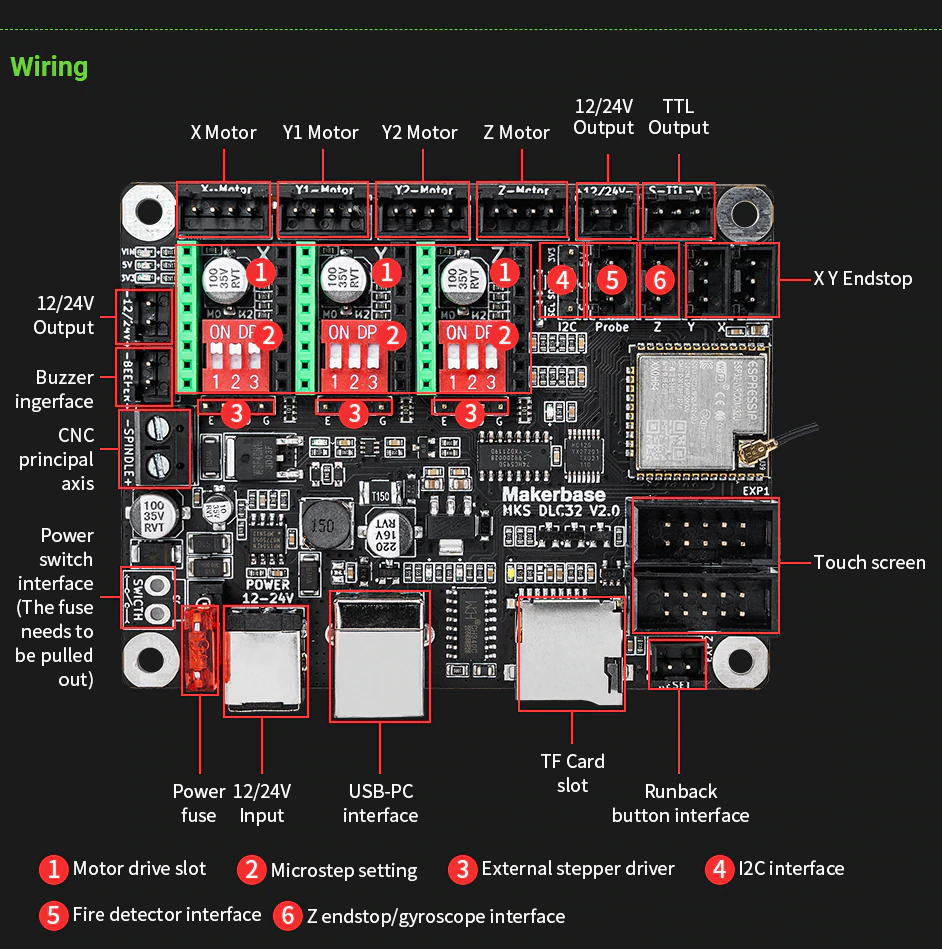
¶ MakerBase MKS DLC32

¶ Helpful hints for working with this hardware
-
Github Page (has some rough PDF schematic)
-
Github Firmware Page (has the open source original firmware)(LCD TouchScreen data is available to be ported into a special "only MKS DLC32" build.
¶ Note
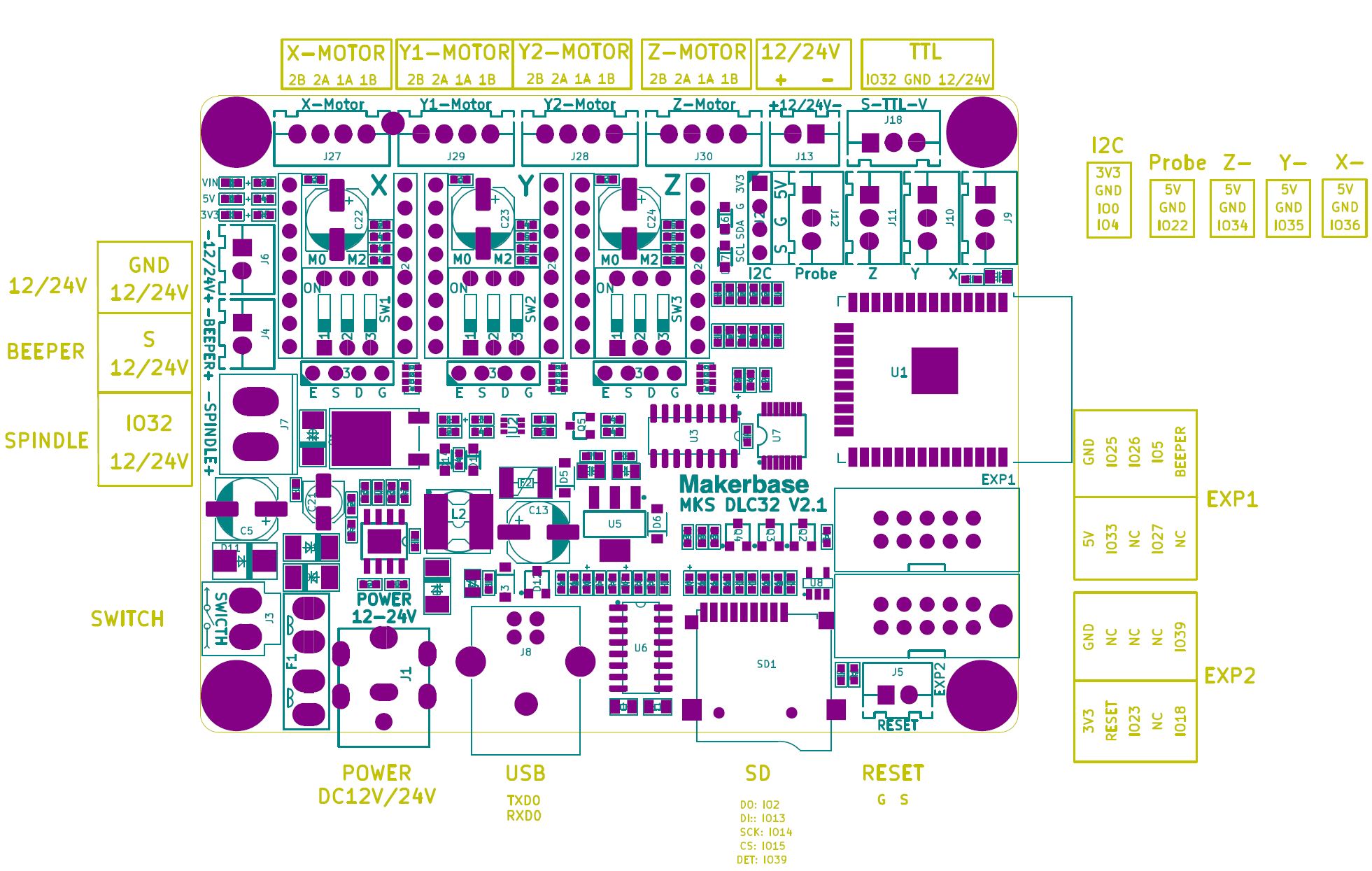
There are some problems with this page caused by third-party edits that are incorrect. I (Mitch) will fix them when I have time. The problems I have noticed so far include: 1. The next note about I2S_STREAM is not actually specific to this hardware. I2S_STREAM does not work well for lasers on any hardware, because of a latency delay between the power control code and the stream buffering of I2S stepping. 2. The stuff about pins i2so.8 - i2so.15 is nonsense; MKS DLC32 has only 8 I2SO pins i2s0.0 - i2so.7. Perhaps the person who wrote that was confusing i2so with the labels IOnn in the picture below.
This hardware does NOT like using I2S_STREAM, it creates a secondary ghost image whenever engraving, however, cutting is absolutely fine and perfect. Recomended use of only I2S_STATIC.
I2S_STATIC Works Flawlessly all functions!
This hardware does not have UART capability to communicate with "smart" drivers, all driver amperage must be set by normal potentiometer method. HOWEVER one person has had success in using sensorless homing by jumping the DIAG pin on a TMC2209 directly from the driver to the GPIO of the corresponding endstop to detecting the stall occurrence. While not a method of UART communiccation for smart features, it can be used to do sensorless homing. The config must be re-written for that feature, and further tested.
¶ MKS Displays
FluidNC does not and will not support the displays that typically ship with this controller. The displays are incompatible with the way FluidNC supports displays.
¶ Pin Numbers
Pin number for latest Version of hardware (V 2.1)

¶ In Numerical Order:
- gpio.0 I2C_SDA
- gpio.1 TXD0
- Used for USB/Serial
- gpio.2
- Used for wifi debug led
- gpio.3 RXD0
- Used for USB/Serial
- gpio.4 I2C_SCL
- gpio.5 LCD_EN
- gpio.12 LCD_MISO/BTN_ENC2
- gpio.13 LCD_MOSI/BTN_ENC
- gpio.14 SPI_CLK
- gpio.15 SPI_CS / SPI_SS
- gpio.16 I2S_BCK
- gpio.17 I2S_WS
- gpio.18 LCD_SCK
- gpio.19 LCD_MISO
- gpio.21 I2S_DATA
- gpio.22 PROBE_PIN
- gpio.23 LCD_MOSI
- gpio.25 LCD_CS (On EXP1 via AHCT125 buffer. Output only)
- gpio.26 TOUCH_CS (On EXP1 via AHCT125 buffer. Output only)
- gpio.27 LCD_RST (On EXP1 via AHCT125 buffer. Output only)
- gpio.32 Spindle or TTL signal
- GPIO32 that is located at TTL section, will deliver up to 5v of power to trigger the laser, this is how you get PWM control is by the firmware varying the voltage.
- GPIO32 at the spindle location is a controlable Ground only, this is how IT controls spindle RPM when being used for a mill
- gpio.33 LCD_RS
- gpio.34 z- (input only)
- gpio.35 Y- (input only)
- gpio.36 X- (input only)
- gpio.39 SDCARD_DET_PIN (input only)
- i2so.0 shared_stepper_disable_pin
- i2so.1 X_STEP
- i2so.2 XDIR
- i2so.3 Z_STEP
- i2so.4 Z_DIR
- i2so.5 Y_STEP
- i2so.6 Y_DIR
- i2so.7 Beeper / EXP1 LCD Beeper (shared)
- i2so.8 Being used as a ground
- i2so.10 +5v for the I2 Chip
- i2so.11 I2S_BCK (communication with I2S chip)
- i2so.12 I2S_WS (same as above)
- i2so.13 Also being used as a ground
- i2so.14 I2S_DATA (communication with I2S chip)
- i2so.15 XYZ_EN (Shared, not needed in config to engage)
¶ In Group use order
-
gpio.1 TXD0
- Used for USB/Serial
-
gpio.3 RXD0
- Used for USB/Serial
-
gpio.0 I2C_SDA
-
gpio.4 I2C_SCL
-
gpio.32 Spindle or TTL signal (use TTL for laser)
- GPIO32 that is located at TTL section, will deliver up to 5v of power to trigger the laser, this is how you get PWM control is by the firmware varying the voltage.
- GPIO32 at the spindle location is a controlable Ground only, this is how IT controls spindle RPM when being used for a mill
-
gpio.21 I2S_DATA
-
gpio.22 PROBE_PIN
-
gpio.18 LCD_SCK
-
gpio.19 LCD_MISO
-
gpio.23 LCD_MOSI
-
gpio.33 LCD_RS
-
gpio.5 LCD_EN
-
gpio.27 LCD_RST
-
gpio.25 LCD_CS
-
gpio.26 TOUCH_CS
-
i2so.7 BEEPER
-
gpio.15 SPI_CS / SPI_SS
-
gpio.39 SDCARD_DET_PIN (input only)
-
gpio.12 LCD_MISO/BTN_ENC2
-
gpio.13 LCD_MOSI/BTN_ENC
-
gpio.14 SPI_CLK
-
gpio.16 I2S_BCK
-
gpio.17 I2S_WS
-
gpio.21 I2S_DATA
-
gpio.34 z- (input only)
-
gpio.35 Y- (input only)
-
gpio.36 X- (input only)
-
i2so.0 shared_stepper_disable_pin
-
i2so.1 X_STEP
-
i2so.2 X_DIR
-
i2so.3 Z_STEP
-
i2so.4 Z_DIR
-
i2so.5 Y_STEP
-
i2so.6 Y_DIR
-
i2so.7 Beeper / EXP1 LCD Beeper (shared)
-
i2so.8 Being used as a ground
-
i2so.10 +5v for the I2 Chip
-
i2so.11 I2S_BCK (communication with I2S chip)
-
i2so.12 I2S_WS (same as above)
-
i2so.13 Also being used as a ground
-
i2so.14 I2S_DATA (communication with I2S chip)
-
i2so.15 XYZ_EN (Shared, not needed in config to engage)
¶ Example Config
board: MKS-DLC32
name: K40 MOD
meta: 2022-12-27 by Tong

kinematics:
  Cartesian:

stepping:
  engine: I2S_STATIC
#Static only, Stream Produces a second "ghost line" when doing engraving/Filling
  idle_ms: 254
  pulse_us: 6
  dir_delay_us: 10
  disable_delay_us: 0
axes:
  shared_stepper_disable_pin: I2SO.0
  x:
    steps_per_mm: 157.500
    max_rate_mm_per_min: 5000.000
    acceleration_mm_per_sec2: 1000.000
    max_travel_mm: 313.000
    soft_limits: true
    homing:
      cycle: 1
      positive_direction: false
      mpos_mm: 0.000
      feed_mm_per_min: 300.000
      seek_mm_per_min: 6000.000
      settle_ms: 500
      seek_scaler: 1.100
      feed_scaler: 1.100

    motor0:
      limit_neg_pin: gpio.36
      hard_limits: false
      pulloff_mm: 1.000
      stepstick:
        step_pin: I2SO.1
        direction_pin: I2SO.2:low

  y:
    steps_per_mm: 157.500
    max_rate_mm_per_min: 5000.000
    acceleration_mm_per_sec2: 1000.000
    max_travel_mm: 230.000
    soft_limits: true
    homing:
      cycle: 1
      positive_direction: false
      mpos_mm: 0.000
      feed_mm_per_min: 300.000
      seek_mm_per_min: 6000.000
      settle_ms: 500
      seek_scaler: 1.100
      feed_scaler: 1.100

    motor0:
      limit_neg_pin: gpio.35
      hard_limits: false
      pulloff_mm: 1.000
      stepstick:
        step_pin: I2SO.5
        direction_pin: I2SO.6:high

  z:
    steps_per_mm: 157.750
    max_rate_mm_per_min: 12000.000
    acceleration_mm_per_sec2: 500.000
    max_travel_mm: 80.000
    soft_limits: true
    homing:
      cycle: 0
      positive_direction: false
      mpos_mm: 0.000
      feed_mm_per_min: 300.000
      seek_mm_per_min: 1000.000
      settle_ms: 500
      seek_scaler: 1.100
      feed_scaler: 1.100

    motor0:
      limit_neg_pin: gpio.34
      hard_limits: false
      pulloff_mm: 1.000
      stepstick:
        step_pin: I2SO.3
        direction_pin: I2SO.4

i2so:
  bck_pin: gpio.16
  data_pin: gpio.21
  ws_pin: gpio.17

spi:
  miso_pin: gpio.12
  mosi_pin: gpio.13
  sck_pin: gpio.14

sdcard:
  cs_pin: gpio.15
  card_detect_pin: gpio.39

control:
  safety_door_pin: NO_PIN
  reset_pin: NO_PIN
  feed_hold_pin: NO_PIN
  cycle_start_pin: NO_PIN
  macro0_pin: gpio.33:low:pu
  macro1_pin: NO_PIN
  macro2_pin: NO_PIN
  macro3_pin: NO_PIN

macros:
  startup_line0:
  startup_line1:
  macro0: $SD/Run=lasertest.gcode
  macro1: $SD/Run=home.gcode
  #These are examples
  macro2:
  macro3:

coolant:
  flood_pin: NO_PIN
  mist_pin: NO_PIN
  delay_ms: 0

probe:
  pin: gpio.22
  check_mode_start: true

Laser:
  pwm_hz: 5000
#For software PWM control on K40, IN on TTL connection, G next to IN to G on TTL. No need for Enable
  output_pin: gpio.32
  enable_pin: NO_PIN
  disable_with_s0: false
  s0_with_disable: false
  tool_num: 0
  speed_map: 0=7.500% 2200=100.000%
# 165=1mA (not enough to fire), 880=9mA 2200=16mA
# Set your own MAX and Minimum,
# Change max until desired MAX mA on gauge
# Change min until laser just before laser fires.

user_outputs:
  analog0_pin: NO_PIN
  analog1_pin: NO_PIN
  analog2_pin: NO_PIN
  analog3_pin: NO_PIN
  analog0_hz: 5000
  analog1_hz: 5000
  analog2_hz: 5000
  analog3_hz: 5000
  digital0_pin: NO_PIN
  digital1_pin: NO_PIN
  digital2_pin: NO_PIN
  digital3_pin: NO_PIN

start:
  must_home: true

# 5,18,19,22,23,25,26,27,32,33,39,I2SO.7
# SDA 0 / SCL 4
¶ Laser Use on K40
¶ To hardwire your machine:
Wire power to 24v on PSU (+ and -), Note: it is highly recomended you use an external PSU as to not overload the already weak Stock PSU. Wire: From MKS DLC32 TTL and it's Ground from board directly TO: PSU IN and the closest Ground to IN. Jumper any other wires that are required to get your laser to fire (P+ and P-) (K- and K+) if equiped, unless you are using switches to trigger those already. NO OTHER WIRING REQUIRED. You now have full PWM control of Laser. GPIO32 that is located at TTL section, will deliver up to 5v of power to trigger the laser, this is how you get PWM control is by the firmware varying the voltage. GPIO32 at the spindle location is a controlable Ground only, this is how IT controls spindle RPM when being used for a mill.
¶ Note
This hardware does NOT like using I2S_STREAM, it creates a secondary ghost image whenever engraving, however, cutting is absolutely fine and perfect. Recomended use of only I2S_STATIC.
¶ Settings correct PWM
As stated in the configuration above: You can absolutely tune in your power use with you mA meter in firmware using: speed_map: 0=P.PPP% VVVV=100.000%
VVVV: use this value to try and find your confortable max with your mA meter for your maximum power. The lower the Value, the higher the mA on your meter. Sugested Start Value at 3000, until you get your desired mA. (2200 produced 16mA usage on my setup)
P.PPP%: use this value to tune in how high of a percentage that trigers your laser. 7.300% was 1mA on my meter but not enough to triger the laser to fire, however when dither engraving, produced a perfect dither at 10% forward. (see OMTech's Material Test Card for testing: https://omtechlaser.com/pages/downloads)
¶ FAQ
-
Is there a way to hack in another motor? Not stepper motors. This controller uses an I2S chip to output steps, so it must use an I2S stepping engine . You cannot use GPIO
-
Can I use an RC Servo? Yes, you just need to find an output pin. The
LCD_CSpin on connector EXP1 has been successfully used. This is gpio.25. The input pins have R/C filters to reduce noise. These should not be used for any PWM application like RC Servos. -
Booloader not active See this message on Github