¶ MKS LS ESP32 Pro
- Company Link
- Documentation
- Support
The FluidNC developers do not have a copy of this board and cannot easily support it. The config file shown below was posted on Discord by a user. Much of the information below comes from reading the schematic.
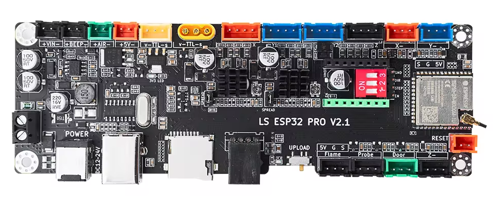
This board uses an ESP32-S3 processor. It is optimized for laser gantries, with two on-board TMC2209 driver chips for the X and Y1/Y2 motor connectors and a stepstick socket for an optional third driver for the Z motor connector. The two Y motor connectors are driven in parallel by the same TMC2209. It has an "air assist" output and a "flame sensor" input.
The TMC2209 chips appear to be setup for standalone mode configuration, with the X UART CS (GPIO 19) pin connected directly to the X driver's PDN_UART pin and Y UART CS (GPIO 20) connected to the Y driver's PDN_UART. It might be possible to perform UART-mode configuration by assigning them to separate UART channels, but my guess is that the design intent was to use the TMC2209s in standalone mode. Each has a separate potentiometer for controlling the current.
As further evidence of standalone configuration, each TMC2209 chip has a jumper to pull the SPREAD pin high, allowing hardware selection of the SpreadCycle (jumper installed) vs StealthChop operating mode.
The two CS pins could be used for enabling standstill power reduction by driving them low. The schematic shows the possibility of both pullup and pulldown resistors on the two PDN_UART pins, but (as with all MKS schematics) the values are not shown, so we do not know which are populated, thus the default pin state is unknown. There is an unclear table showing some pin connections. It might indicate that PDN_UART is pulled down through 20K, which would put the TMC2209 in auto-standstill power reduction mode.
A pendant could be connected via the RJ11 socket. See the schematic for the pin assignments.
The SDCard slot has full 4-data-pin SD wiring, but FluidNC only supports SPI mode SDCard access with the SD_D0 line used as MISO and the SD_CMD line used as MOSI. The SD socket has a selectable supply voltage controlled by GPIO 9, so it can be used with 1.8V SD Cards in addition to the 3.3V cards that are more commonly used with FluidNC controllers.
¶ Pins
- gpio.1 Air Assist
- gpio.2 LC
- gpio.4 Z Dir
- gpio.5 Z Step
- gpio.6 Y Dir
- gpio.7 Y Step
- gpio.8 XYZ Enable
- gpio.9 SD VCC Select
- gpio.10 SD Detect
- gpio.11 SD D1
- gpio.12 SD D0 (SPI MISO)
- gpio.13 SD Clk
- gpio.14 SD CMD (SPI MOSI)
- gpio.15 X Dir
- gpio.16 X Step
- gpio.17 TXD1
- gpio.18 RXD1
- gpio.19 X UART CS
- gpio.20 Y UART CS
- gpio.21 SD D3
- gpio.47 SD D2
- gpio.35 PWM
- gpio.36 Flame
- gpio.38 Probe
- gpio.39 X- LImit
- gpio.40 y- Limit
- gpio.41 Z- Limit
- gpio.42 Beeper
¶ Input Circuits
The X, Y and Z limit inputs are non-inverting with RC filtering and on-board external pullup resistors. Each has a diode in series to protect the against voltages above 3.3V. The circuit can be driven from most types of switches and sensors.
The Door, Flame and Probe inputs have similar RC filtering, but instead of series diode protection, they have zener clamp diodes. They are similarly compatible with many switches, but it is probably best to ensure that the input voltage does not exceed 4V.
Consult the schematic for the actual circuit diagrams.
¶ Output Circuits
The Beeper output has +12V on pin 2 and pin 1 is driven to ground through a bipolar transistor when the BEEPER signal (GPIO 42) is high.
The LED output has +5V on pin 2 and pin 1 is driven to ground through a MOSFET rated at 5.8A when the PWM signal (GPIO 35) is high.
The AirAssist output has +12V on pin 2 and pin 1 is driven to ground through a MOSFET rated at 42A when the PWM signal (GPIO 1) is high. It has an associated LED that lights when the output is low.
The LC output (probably Laser-TTL) is driven between 0V and 5V via a driver chip that can source or sink 50 mA, controlled (non-inverting) by the LC signal (GPIO 2). There are two Laser TTL connectors with different connector types, each with GND, 12V and TTL signals. According to the schematic, they are connected in parallel. The only difference appears to be that the larger "50W" one has larger pins that can supply more power to the laser via GND and 12V.
¶ Example config
The motors are configured as stepstick: sections, not tmc2209: sections, because the TMC2209 chips use standalone (hardware based) configuration instead of UART wiring. You could add a Z axis using the Z step and direction pins shown above if you have a stepstick module in the Z driver socket.
name: Twotrees TTS-10 Pro
board: MKS LS ESP32 PRO v2.1
stepping:
  engine: RMT
  idle_ms: 25
  pulse_us: 10
  dir_delay_us: 0
  disable_delay_us: 0
spi:
  miso_pin: gpio.12
  mosi_pin: gpio.14
  sck_pin: gpio.13
sdcard:
  cs_pin: gpio.21
  card_detect_pin: gpio.10
  frequency_hz: 8000000
axes:
  shared_stepper_disable_pin: gpio.8
  x:
    steps_per_mm: 80
    max_rate_mm_per_min: 30000
    acceleration_mm_per_sec2: 2500
    max_travel_mm: 301
    soft_limits: true
    homing:
      cycle: 1
      positive_direction: false
      mpos_mm: 0
      feed_mm_per_min: 300
      seek_mm_per_min: 1000
      settle_ms: 250
      seek_scaler: 1.1
      feed_scaler: 1.1
    motor0:
      hard_limits: true
      pulloff_mm: 2
      limit_neg_pin: gpio.39:pu:low
      limit_pos_pin: NO_PIN
      limit_all_pin: NO_PIN
      stepstick:
        step_pin: gpio.16
        direction_pin: gpio.15
        disable_pin: NO_PIN
        ms1_pin: NO_PIN
        ms2_pin: NO_PIN
        ms3_pin: NO_PIN
  y:
    steps_per_mm: 80
    max_rate_mm_per_min: 30000
    acceleration_mm_per_sec2: 2500
    max_travel_mm: 301
    soft_limits: true
    homing:
      cycle: 1
      positive_direction: false
      mpos_mm: 0
      feed_mm_per_min: 300
      seek_mm_per_min: 1000
      settle_ms: 250
      seek_scaler: 1.1
      feed_scaler: 1.1
    motor0:
      hard_limits: true
      pulloff_mm: 2
      stepstick:
        step_pin: gpio.7
        direction_pin: gpio.6
        disable_pin: NO_PIN
        ms1_pin: NO_PIN
        ms2_pin: NO_PIN
        ms3_pin: NO_PIN
      limit_neg_pin: gpio.40:pu:low
      limit_pos_pin: NO_PIN
      limit_all_pin: NO_PIN
junction_deviation_mm: 0.01
arc_tolerance_mm: 0.002
Laser:
  output_pin: gpio.2
  disable_with_s0: true
  s0_with_disable: true
  off_on_alarm: true
  speed_map: 0=0.000% 1000=100.000%
  enable_pin: NO_PIN
start:
  must_home: false
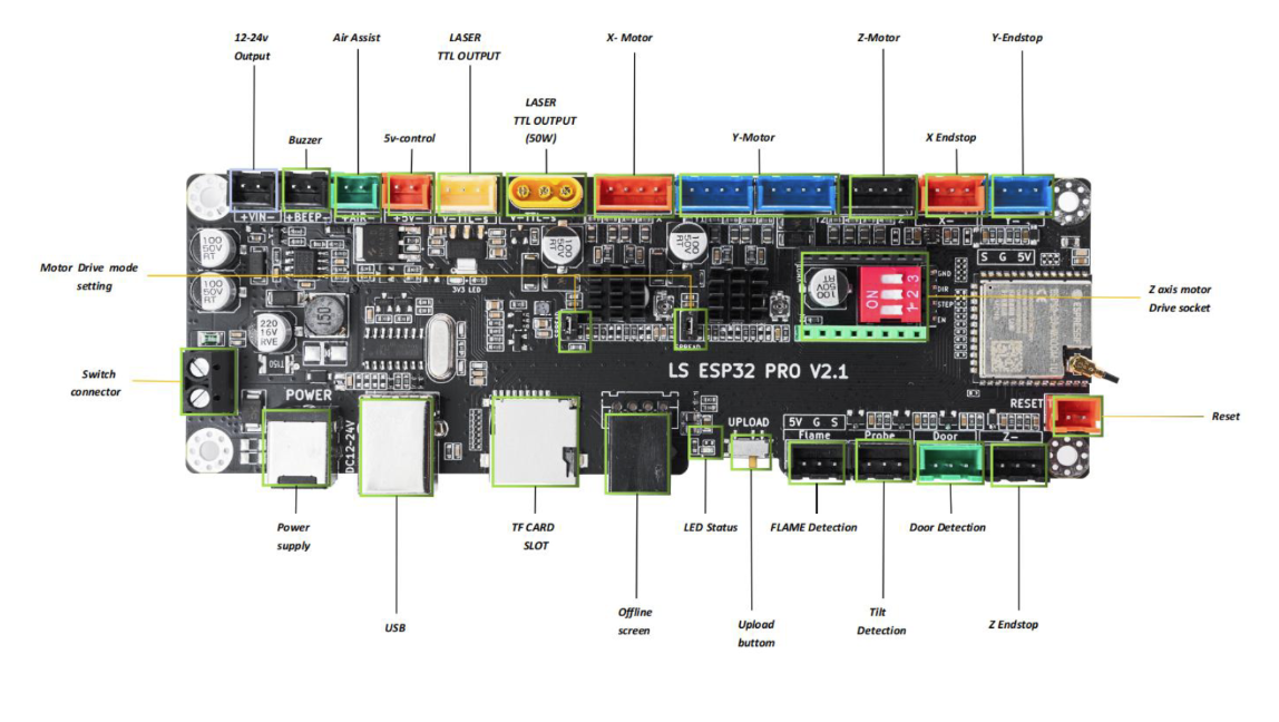
¶ Connector Labels
¶ Description
This uses an ESP32-S3 processor!