¶ MKS Tinybee
Note: The display that sometimes ships with this controller is not supported by FluidNC and probably never will be.
¶ Reference Links
- Github
- Latest Schematic
- Manual
- User-contributed IO Spreadsheet - Discord announcement
- User-contributed IO Spreadsheet
¶ Images
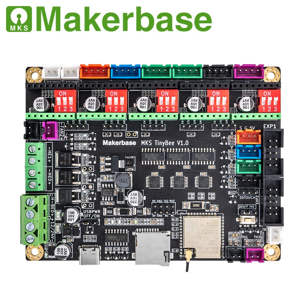
¶ Pinout
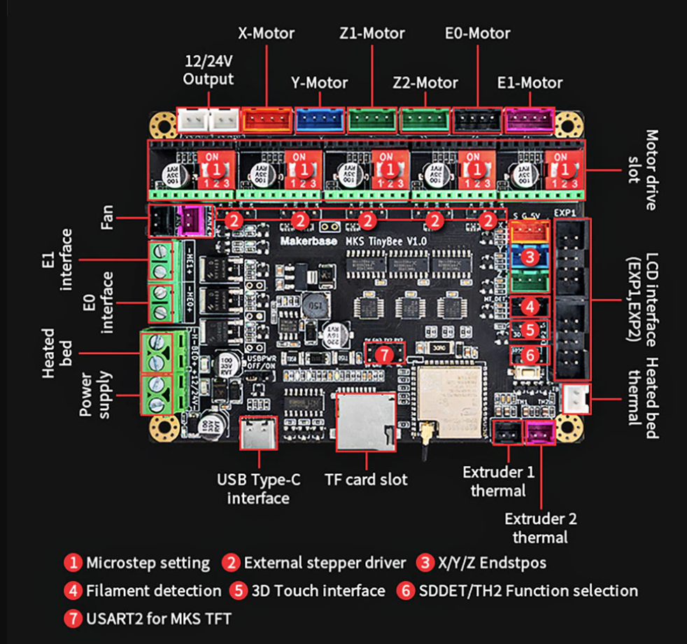
¶ IO Identification
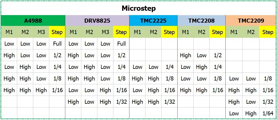
¶ Microstepping
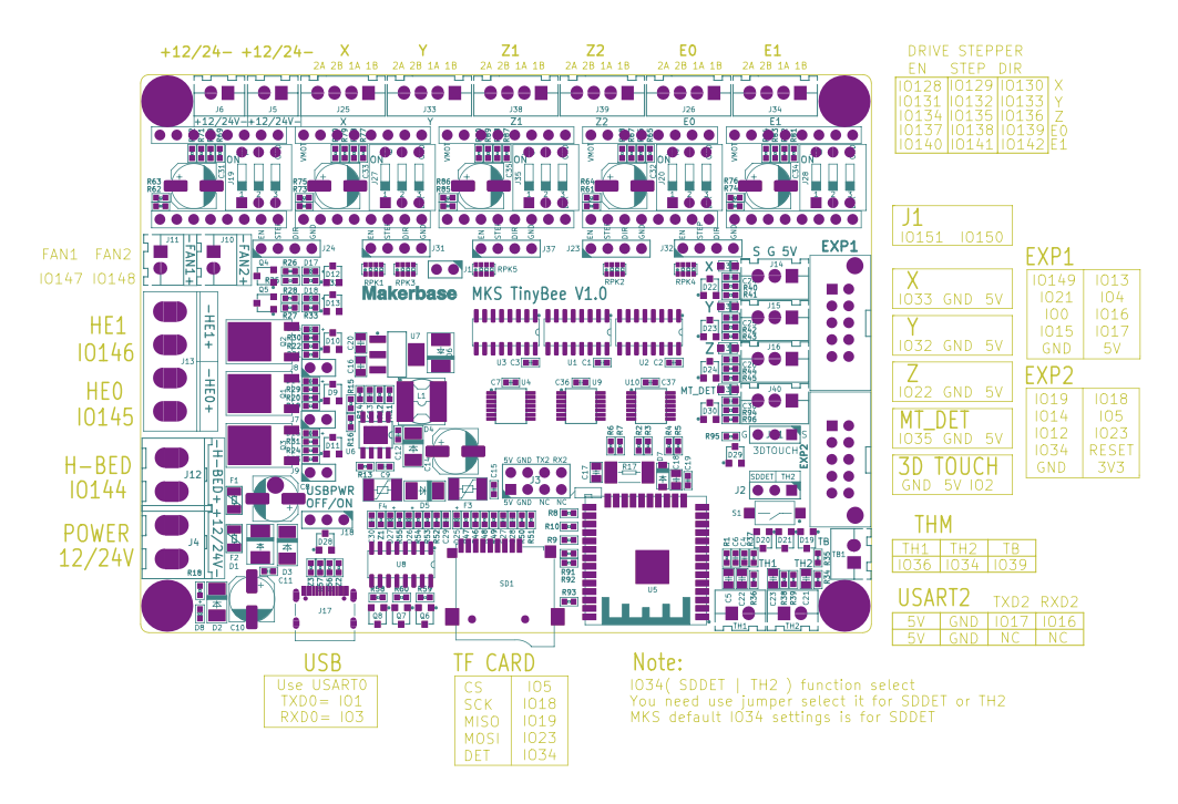
¶ Pins
| Pin | Usage | Notes |
|---|---|---|
| gpio.0 | LCD_D4 | |
| gpio.1 | TXD0 | Used for USB/Serial |
| gpio.2 | 3D_TOUCH | Can only be used as an output due to other circuitry |
| gpio.3 | RXD0 | Used for USB/Serial |
| gpio.4 | LCD_RS | |
| gpio.5 | SPI_CS | SD Card |
| gpio.12 | LCD_MISO/BTN_ENC2 | |
| gpio.13 | LCD_MOSI/BTN_ENC | |
| gpio.14 | LCD_CLK | |
| gpio.15 | LCD_D6 | |
| gpio.16 | LCD_D5 | On USART2, not EXP1 |
| gpio.17 | LCD_D7 | ON USART2, not EXP1 |
| gpio.18 | SPI_CLK | SD Card |
| gpio.19 | SPI_MISO | SD Card |
| gpio.21 | LCD_EN | |
| gpio.22 | Limit Z- | Should be used as an input |
| gpio.23 | SPI_MOSI | SD Card |
| gpio.25 | I2S_BCK | I2S bck_pin: gpio.25 |
| gpio.26 | I2S_WS | I2S ws_pin: gpio.26 |
| gpio.27 | I2S_DATA | I2S data_pin: gpio.27 |
| gpio.32 | Limit Y- | Should be used as an input |
| gpio.33 | Limit X- | Should be used as an input |
| gpio.35 | MT_DET | |
| gpio.34 | SPI_DET or TH2 (Jumper 2) | |
| gpio.36 | (sensor VP) TH1 | Pin 2 |
| gpio.39 | (Sensor VN) TB | Pin 2 |
| i2so.0 | X_EN | |
| i2so.1 | X_STEP | |
| i2so.2 | X_DIR | |
| i2so.3 | Y_EN | |
| i2so.4 | Y_STEP | |
| i2so.5 | Y_DIR | |
| i2so.6 | Z_EN | |
| i2so.7 | Z_STEP | |
| i2so.8 | Z_DIR | |
| i2so.9 | E0_EN | |
| i2so.10 | E0_STEP | |
| i2so.11 | E0_DIR | |
| i2so.12 | E1_EN | |
| i2so.13 | E1_STEP | |
| i2so.14 | E1_DIR | |
| i2so.15 | (N/C) | |
| i2so.16 | H-BED | Driver mosfet G024N03 - 30V/100A. Cannot be used for PWM. |
| i2so.17 | H-E0 | Driver mosfet HY1403D - 30V/42A. Cannot be used for PWM. |
| *i2so.18 | H-E1 | Driver mosfet HY1403D - 30V/42A. Cannot be used for PWM. |
| i2so.19 | H-FAN1 | |
| i2so.20 | FAN2 | |
| i2so.21 | BEEPER | |
| i2so.22 | OUT_Q150 | |
| i2so.23 | OUT_Q151 | |
¶ Inputs
The temperature sensor connectors can be used as active low inputs.
- TH2 gpio.34:low
- TH1 gpio.36:low
- TB gpio.39:low
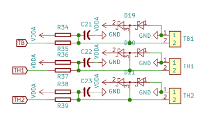
The X,Y and Z limit switch connectors can be used as inputs. They have pullups and should be switched to ground (active low)
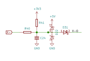
- limit_neg_pin: gpio.22:low
- limit_neg_pin: gpio.32:low
- limit_neg_pin: gpio.33:low
¶ Example Config
board: MKS TinyBee V1.0 XXYYZ
name:

kinematics:
  Cartesian:

i2so:
  bck_pin: gpio.25
  data_pin: gpio.27
  ws_pin: gpio.26

spi:
  miso_pin: gpio.19
  mosi_pin: gpio.23
  sck_pin: gpio.18

sdcard:
  cs_pin: gpio.5
  # uses TH2 IO34 active low - MAKE SURE jumper J2 is set to SDDET!!!
  card_detect_pin: gpio.34:low

stepping:
  engine: I2S_STATIC
  idle_ms: 255
  pulse_us: 4
  dir_delay_us: 1
  disable_delay_us: 2

axes:
  x:
    steps_per_mm: 40
    max_rate_mm_per_min: 8000.000
    acceleration_mm_per_sec2: 80.000
    max_travel_mm: 2500.000
    soft_limits: false
    homing:
      cycle: 2
      positive_direction: false
      mpos_mm: 0.000
      feed_mm_per_min: 300.000
      seek_mm_per_min: 1500.000
      settle_ms: 500
      seek_scaler: 1.100
      feed_scaler: 1.100

    motor0:
      limit_neg_pin: gpio.33:low:pu
      hard_limits: true
      pulloff_mm: 4.000
      stepstick:
        step_pin: I2SO.1
        direction_pin: I2SO.2
        disable_pin: I2SO.0

    # use E0 driver for 2nd X axis motor
    motor1:
      hard_limits: true
      pulloff_mm: 4.000
      stepstick:
        step_pin: I2SO.10
        direction_pin: I2SO.11
        disable_pin: I2SO.9

  y:
    steps_per_mm: 40
    max_rate_mm_per_min: 8000.000
    acceleration_mm_per_sec2: 70.000
    max_travel_mm: 1250.000
    soft_limits: false
    homing:
      cycle: 3
      positive_direction: false
      mpos_mm: 0.000
      feed_mm_per_min: 300.000
      seek_mm_per_min: 2000.000
      settle_ms: 500
      seek_scaler: 1.100
      feed_scaler: 1.100

    motor0:
      limit_neg_pin: gpio.32:low:pu
      hard_limits: false
      pulloff_mm: 4.000
      stepstick:
        step_pin: I2SO.4
        direction_pin: I2SO.5
        disable_pin: I2SO.3

    # use E1 driver for 2nd Y axis motor
    motor1:
      limit_neg_pin: NO_PIN
      hard_limits: false
      pulloff_mm: 4.000
      stepstick:
        step_pin: I2SO.13
        direction_pin: I2SO.14
        disable_pin: I2SO.12

  z:
    steps_per_mm: 200.000
    max_rate_mm_per_min: 8000.000
    acceleration_mm_per_sec2: 60.000
    max_travel_mm: 80.000
    soft_limits: false
    homing:
      cycle: 1
      positive_direction: true
      mpos_mm: 0.000
      feed_mm_per_min: 300.000
      seek_mm_per_min: 500.000
      settle_ms: 500
      seek_scaler: 1.100
      feed_scaler: 1.100

    motor0:
      limit_pos_pin: gpio.22:low:pu
      hard_limits: true
      pulloff_mm: 3.000
      stepstick:
        step_pin: I2SO.7
        direction_pin: I2SO.8
        disable_pin: I2SO.6

control:
  safety_door_pin: NO_PIN
  # on MT_DET connector
  reset_pin: gpio.35:low
  # on TH1 connector
  feed_hold_pin: gpio.36:low
  # on TB connector
  cycle_start_pin: gpio.39:low
  macro0_pin: NO_PIN
  macro1_pin: NO_PIN
  macro2_pin: NO_PIN
  macro3_pin: NO_PIN

coolant:
  # Heated Bed Terminal Block
  flood_pin: i2so.16
  # HE0 Terminal Block
  mist_pin: i2so.17
  delay_ms: 0

# spindle PWM signal
PWM:
  pwm_hz: 2500
  # on EXP1 IO15 connector.
  # note IO15 will give some short pulses on boot, which may activate spindle
  # use IO17 on EXP1 to avoid
  output_pin: gpio.15:high
  s0_with_disable: true
  tool_num: 0
  spinup_ms: 4000
  spindown_ms: 4000
  speed_map: 0=0.000% 12000=100.000%

Laser:
  pwm_hz: 5000
  # on 3D Touch connector (has pdwn + PWM)
  output_pin: gpio.2:high:pd
  s0_with_disable: true
  tool_num: 1
  speed_map: 0=0.000% 1000=100.000%

start:
  must_home: false
¶ Probe Example
gpio.35 is the MT_DET port. Make sure it is not assigned to another function in your config.
probe:
  pin: gpio.35:pu:low
  check_mode_start: true
¶ RS485 Spindle Control
Coming soon...see this Discord discussion MKS_TinyBee.
Or see this discussion.
uart2:
  txd_pin: gpio.4
  rxd_pin: gpio.13
  rts_pin: NO_PIN
  baud: 9600
  mode: 8N1

H100:
  uart_num: 2
  modbus_id: 1
  tool_num: 0
  speed_map: 0=0% 0=25% 6000=25% 24000=100%
  off_on_alarm: false
¶ Modifications to allow UART control of drivers
WARNING: depending on the drivers you are using, you can destroy your board if you don not set the third DIP switch on every driver to OFF
To allow UART control you need to link all of the driver RST pins together on the back of the board. The pin directly to the left of the RST pin (labelled "P") is also connected to the RST pin, which can make point-to-point wiring easier.
Connect one RST or P pin to the RX2 pin, and another RST or P pin to TX2 with a resistor. The RX2 and TX2 pins are the top two left-most pins when viewed from the back. Usually this resistor is a 1K, however I had to use 330R. You may need to try a higher or lower value resistor to get yours to work.
Set all your DIP switches to OFF. Then assign addresses using the 1 & 2 dip switches.
0 = OFF OFF
1 = ON- OFF
2 = OFF ON
3 = ON- ON
There are 5 drivers on the board, however drivers can share the same address.
uart2:
  txd_pin: gpio.17
  rxd_pin: gpio.16
  baud: 115200
  mode: 8N1
Set each motor to use UART in the usual way, something like this: (you will need to change the addr along with the step, direction and disable pins for each motor)
      tmc_2209:
        uart_num: 2
        addr: 0
        r_sense_ohms: 0.110
        run_amps: 1.200
        hold_amps: 0.800
        microsteps: 4
        stallguard: 0
        stallguard_debug: false
        toff_disable: 0
        toff_stealthchop: 5
        toff_coolstep: 3
        run_mode: StealthChop
        homing_mode: StealthChop
        use_enable: true
        step_pin: I2SO.1
        direction_pin: I2SO.2
        disable_pin: I2SO.0