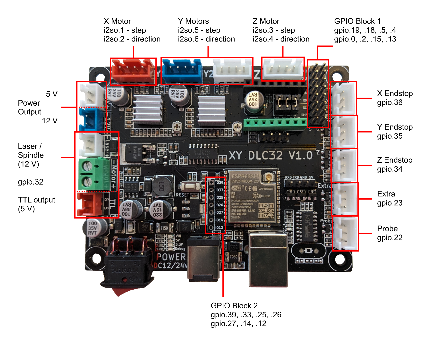
¶ Makerbase XY DLC32 V1.0
The XY DLC32 V1.0 is the predecessor of the MKS DLC32 V2.x and can be found in the Sculpfun S9 laser engraver.

¶ References
- FluidNC configuration file
The config file has not yet been accepted in the repository, therefore the link points to the associated pull request. - GitHub Firmware Page for Sculpfun S9
Hosts the modified version of Grbl_ESP32, that is shipped as firmware with the Sculpfun S9 laser engraver. - GitHub Firmware Page for MKS DLC32
Hosts the firmware for the Makerbase MKS DLC32 board, that is quite similar to the XY DLC32 V1.0. The config files look like they might also be usable with this board.
¶ Important Remarks
¶ Output for Laser / Spindle / TTL
The gpio.32 controls all three sockets at the same time. While the TTL socket delivers up to 5 V, the Laser / Spindle sockets have a switched ground and constant 12 V on the + side.
They are intended to be used with PWM control, either reducing the effective voltage delivered to a Spindle or by using the TTL signal to control a PWM enabled Laser.
¶ Note on Sculpfun S9
The Sculpfun S9 comes with a laser module, that is connected to permanent 12 V and the TTL output. The Laser output is not suitable, since it does not provide effective 12 V, if the power of the laser isn't set to 100%.
However, this leads to the laser fan being active all the time. One option to switch of the fan during stand still is, to connect power to the Laser output controlled by gpio.32 and the PWM signal to a custom pin. Now FluidNC can be configured to use gpio.32 as enable_pin and the custom pin as output_pin.
This configuration variant hasn't been tested yet.
¶ Full Pin Assignment
¶ in numerical order
GPIO pins
- gpio.0 GPIO in block 1, pos 4
- gpio.1 TXD0
- gpio.2 GPIO in block 1, pos 5
- gpio.3 RXD0
- gpio.4 GPIO in block 1, pos 3
- gpio.5 GPIO in block 1, pos 2
- gpio.6 CLK
- gpio.7 SD0
- gpio.8 SD1
- gpio.9 SD2
- gpio.10 SD3
- gpio.11 CMD
- gpio.12 GPIO in block 2, pos 6
- gpio.13 GPIO in block 1, pos 7
- gpio.14 GPIO in block 2, pos 5
- gpio.15 GPIO in block 1, pos 6
- gpio.16 I2S clock (bck_pin)
- gpio.17 I2S word select (ws_pin)
- gpio.18 GPIO in block 1, pos 1
- gpio.19 GPIO in block 1, pos 0
- gpio.21 I2S data (data_pin)
- gpio.22 Probe
- gpio.23 Extra
- gpio.25 GPIO in block 2, pos 2
- gpio.26 GPIO in block 2, pos 3
- gpio.27 GPIO in block 2, pos 4
- gpio.32 Laser / Spindle / TTL
- gpio.33 GPIO in block 2, pos 1
- gpio.34 Z Endstop
- gpio.35 Y Endstop
- gpio.36 X Endstop
- gpio.39 GPIO in block 2, pos 0
I2S pins
- i2so.0 shared stepper disable
- i2so.1 X step
- i2so.2 X direction
- i2so.3 Z step
- i2so.4 Z direction
- i2so.5 Y step
- i2so.6 Y direction
¶ grouped by use
I2S configuration
- gpio.16 I2S clock (bck_pin)
- gpio.21 I2S data (data_pin)
- gpio.17 I2S word select (ws_pin)
I2S pins
- i2so.0 shared stepper disable
- i2so.1 X step
- i2so.2 X direction
- i2so.3 Z step
- i2so.4 Z direction
- i2so.5 Y step
- i2so.6 Y direction
Endstops
- gpio.36 X Endstop
- gpio.35 Y Endstop
- gpio.34 Z Endstop
- gpio.23 Extra
- gpio.22 Probe
Laser Spindle
- gpio.32 Laser / Spindle / TTL
GPIO Block 1
- gpio.19 GPIO in block 1, pos 0
- gpio.18 GPIO in block 1, pos 1
- gpio.5 GPIO in block 1, pos 2
- gpio.4 GPIO in block 1, pos 3
- gpio.0 GPIO in block 1, pos 4
- gpio.2 GPIO in block 1, pos 5
- gpio.15 GPIO in block 1, pos 6
- gpio.13 GPIO in block 1, pos 7
GPIO Block 2
- gpio.39 GPIO in block 2, pos 0
- gpio.33 GPIO in block 2, pos 1
- gpio.25 GPIO in block 2, pos 2
- gpio.26 GPIO in block 2, pos 3
- gpio.27 GPIO in block 2, pos 4
- gpio.14 GPIO in block 2, pos 5
- gpio.12 GPIO in block 2, pos 6