¶ Anolex A-X5.7.3 Controller Board
¶ Overview
The Anolex A-X5.7.3 Controller Board ships with Grbl_Esp32 installed, but is FluidNC-compatible if you want to hack on it a bit. It is powered by a 24V/10A power supply.
This controller board shipped with an Anolex Evo Ultra 2 machine in 2025. Earlier or later controller boards from Anolex may or may not adhere to the pinout found on this A-X5.7.3 board. Anolex does not provide schematics (but has provided some info).
This wiki page is a work in progress, is user-provided, and not official FluidNC information. No warranty expressed or implied. Please consider donating to FluidNC.
¶ Motor Drivers
There are motor drivers (unknown chips with no markings) integrated on the bottom of the board under a removable heat sink. Four-pin stepper connectors are provided for X, Y, Z, and A axes -- there is also a second Y connector and it may be able to drive a dual-motor Y1Y2 axis, but this is untested. There are also five-pin connectors for optional Anolex closed-loop motors.
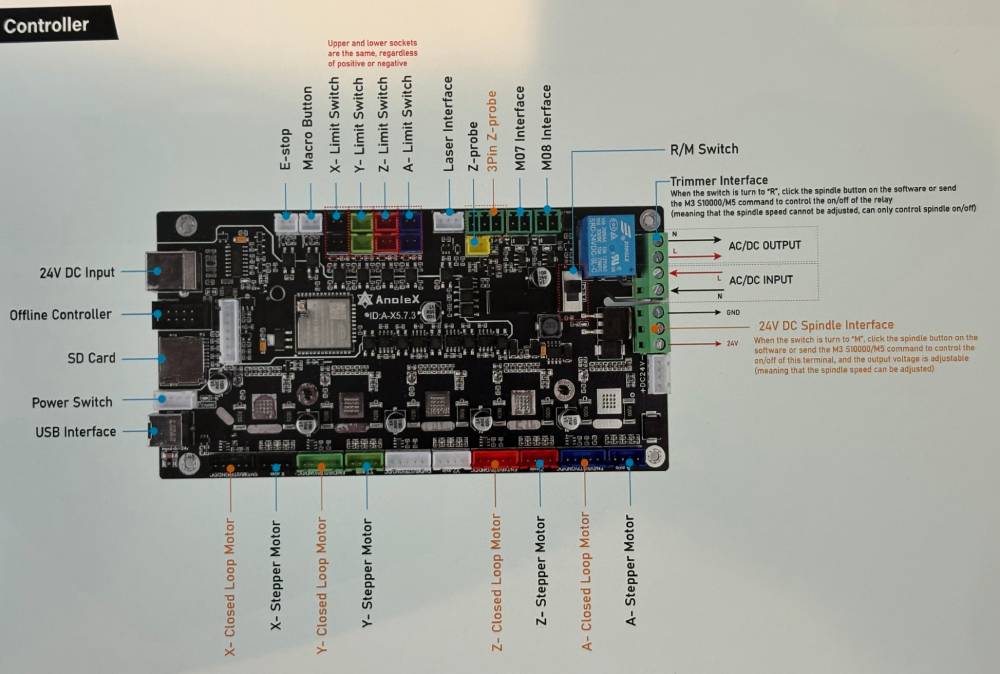
¶ I/O
E-Stop and Macro inputs connect to front-panel switches. Normally-open limit switches are supported for XYZA axes. The "Laser-Interface" 3-pin connector is a PWM output -- this is most-often used to connect to Anolex's optional VFD which is speed controlled by pwm. The Z-probe has two connectors that are paralleled (the 2-pin has GND and PROBE/ and the 3-pin adds a 24V pin). M07 output is for flood (labeled "Water") and M08 is mist (labeled "Air"). All I/O is opto-isolated.
¶ Missing Feature
- RS485 Interface (bummer)
¶ Caution
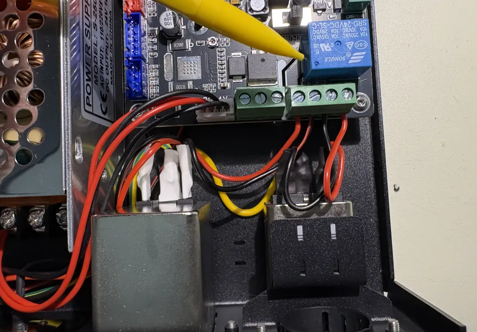
There is a relay to switch AC power for the provided 800-watt router motor. This switches AC to an illegal male connector on the rear panel -- this is a potentially-lethal electrocution hazard -- you have been warned. The AC wires must be removed from the board to ensure safety. Just get a real spindle and VFD and get rid of the cheesy router motor.
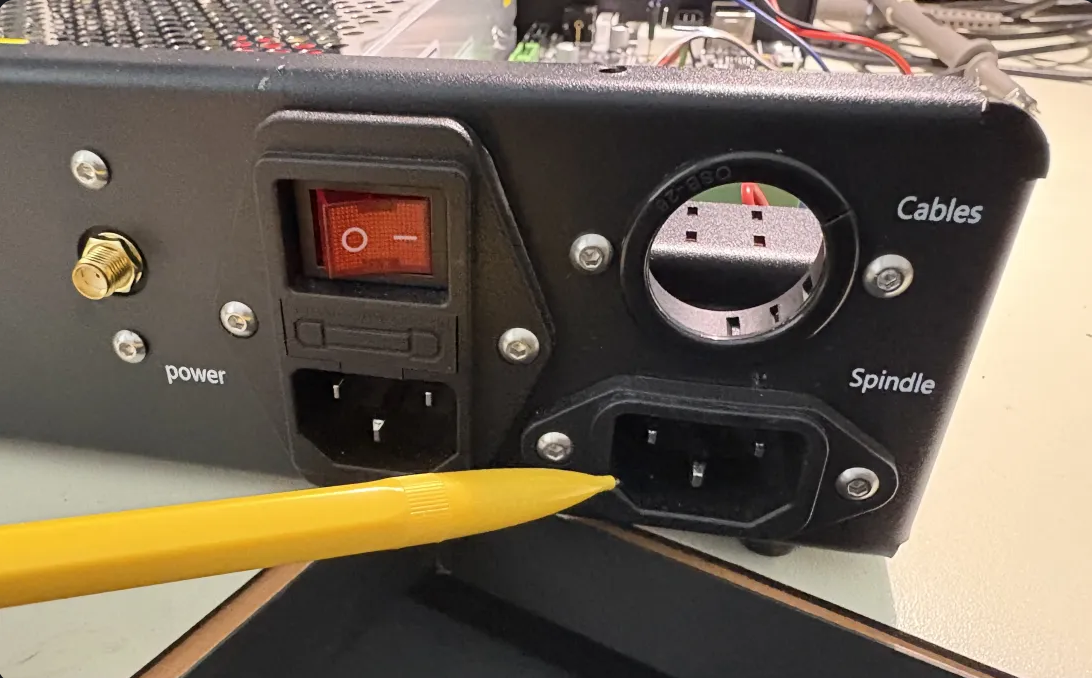
I pulled the four wires from the terminal block below the relay, insulated them with some heat shrink and tucked them out of the way. Alternately, you could just fill the exposed rear-panel connector with a big-o blob of hot-melt glue.
¶ Loading FluidNC
Here is my current config file: Download anolex4030.yaml
I was able to load FluidNC via the web installer on a mac, and also via USB from a win system (using the install bat files).
There was an error and a warning message from FluidNC at boot time:
[MSG:ERR: macro0_pin is active at startup] >>> this is the Macro input (gpio.2)
[MSG:INFO: ALARM: Control Pin Initially On] >>> this is the Probe input (gpio.12)
These two pins seem to depend on the esp's internal pullups for normal operation. However, they are also special esp strapping pins that get latched at boot time and are expected to be low at power-up. Yes, Anolex could have designed it with inverted logic, and should have, but it is what it is. FluidNC must have a somewhat different boot sequence than Grbl_Esp32 (regarding the timing of when the internal pullups are enabled).
You may be able to ignore these messages and clear the alarm state after boot, I am not certain -- I quieted these messages by hacking the wiring on the esp-side of the opto-isolators.
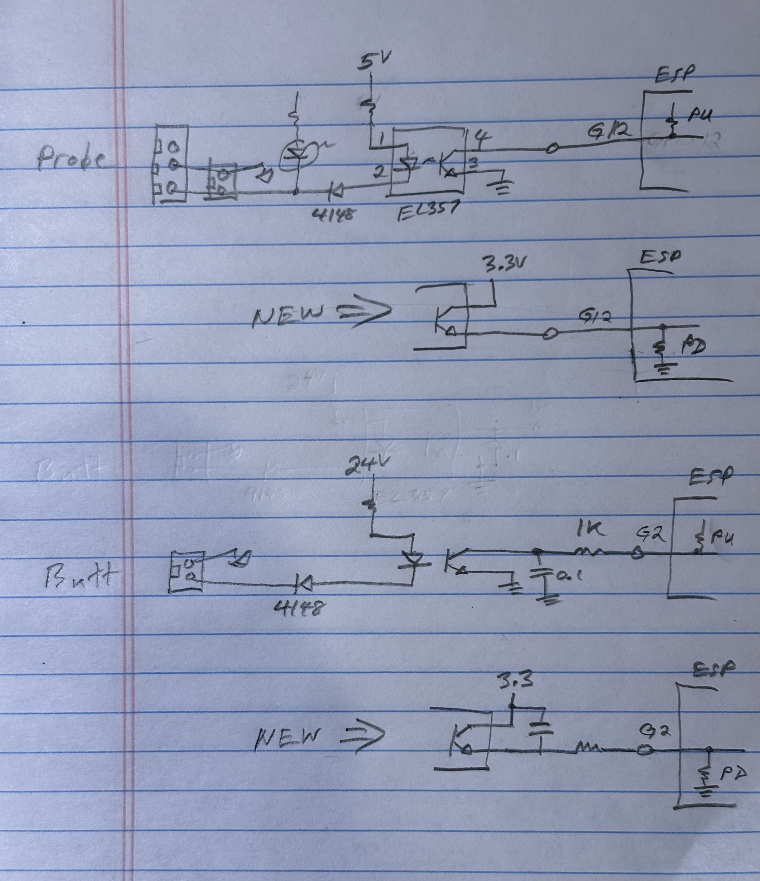
¶ Optional Hacks
If you are handy with a soldering iron, and don't mind hacking on your board, here are the things I added:
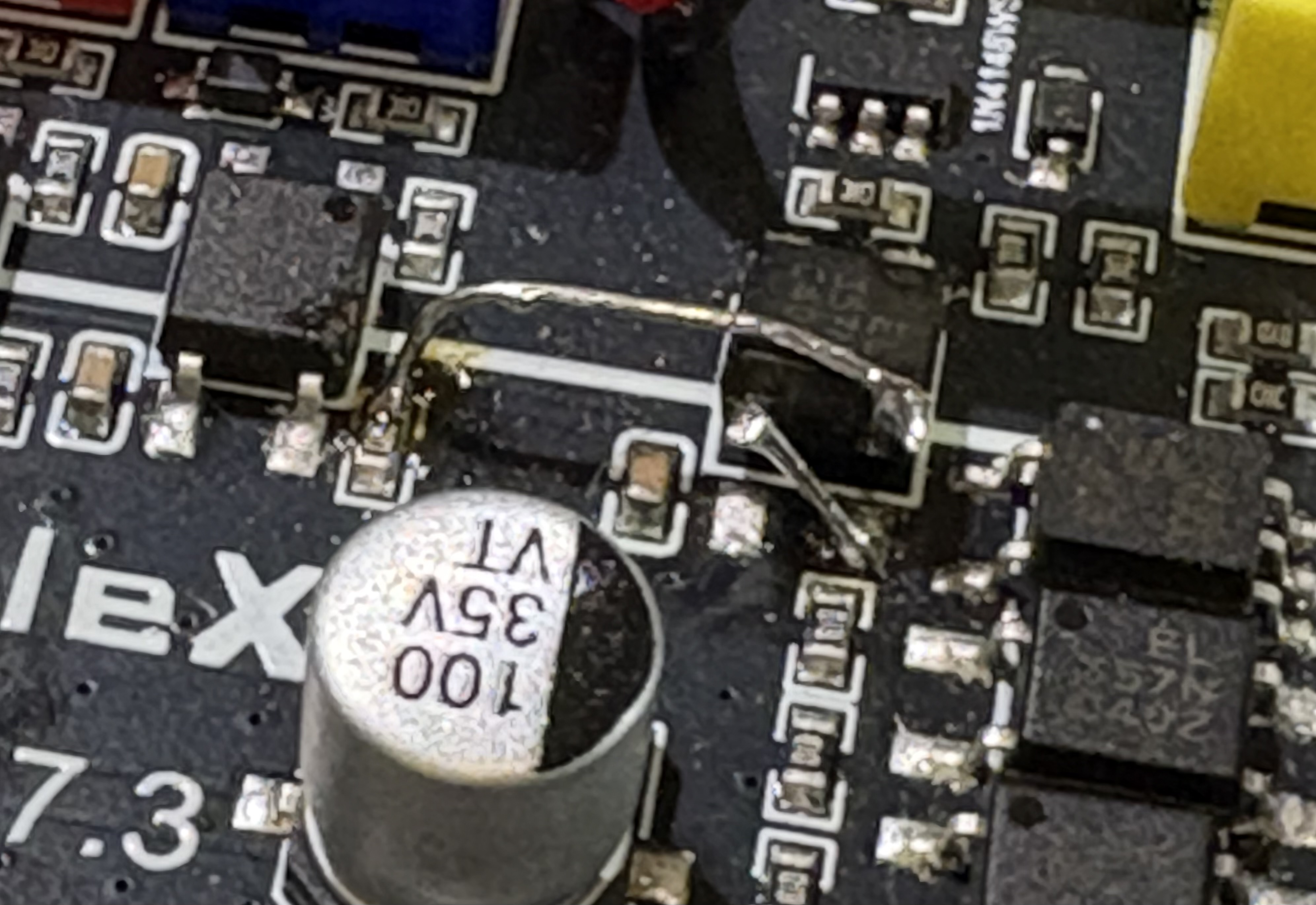
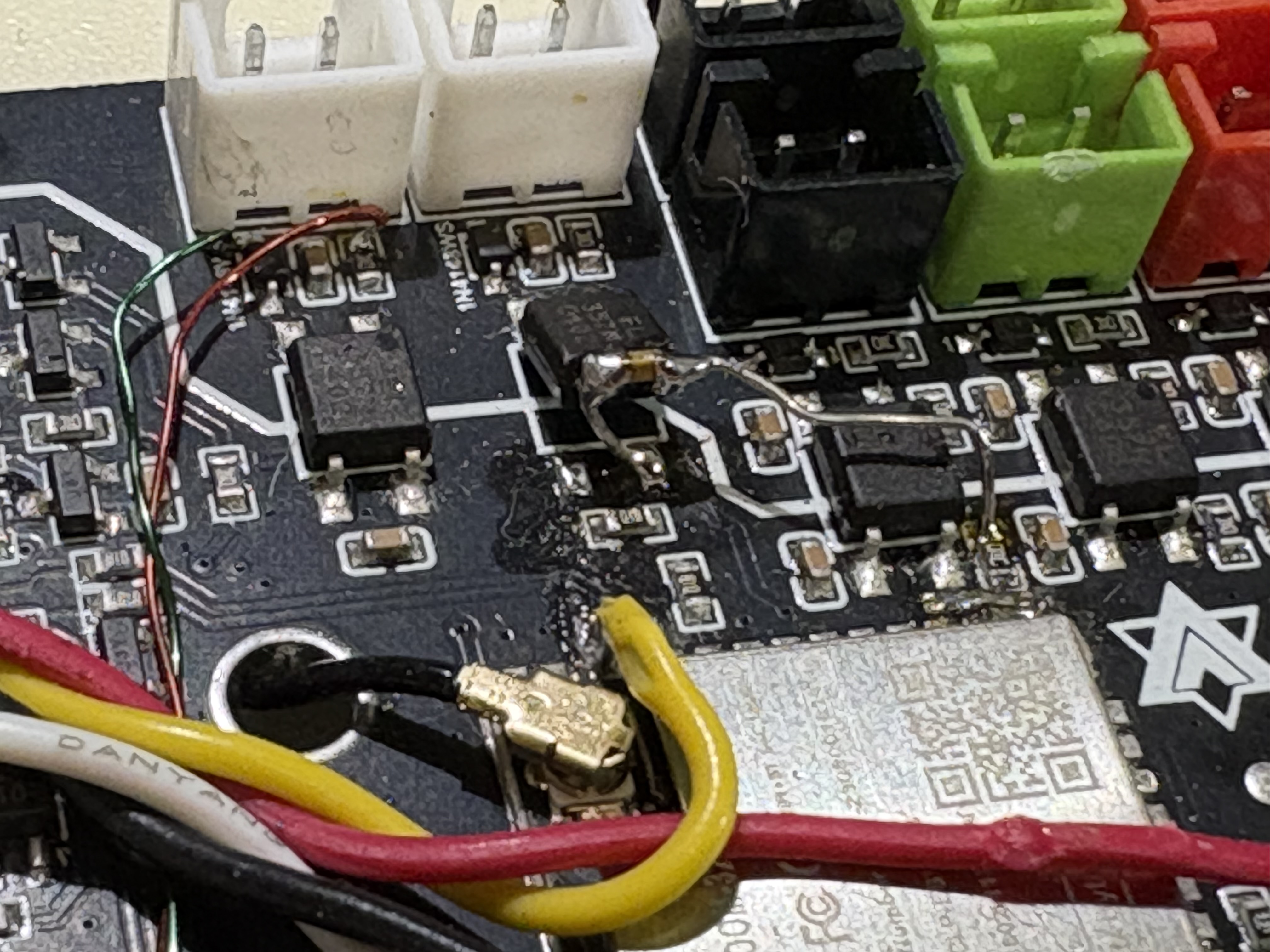
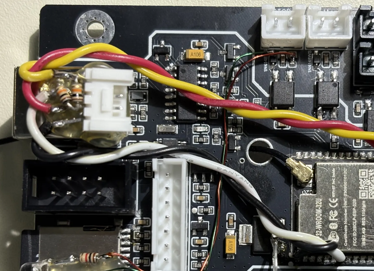
- As mentioned above, the error messages about macro and probe pins can be fixed. The problem is that gpio.12 (probe) and gpio.2 (macro button) need to be open or pulled DOWN at power-up so the esp can latch the state, for some internal esp configuration beyond the scope of this discussion. So I lifted the 2 pins on the esp side of the optos and re-wired it the way it should have been designed. Also, the yaml needs to be changed to gpio.12:high:pd and gpio.2:high:pd.:
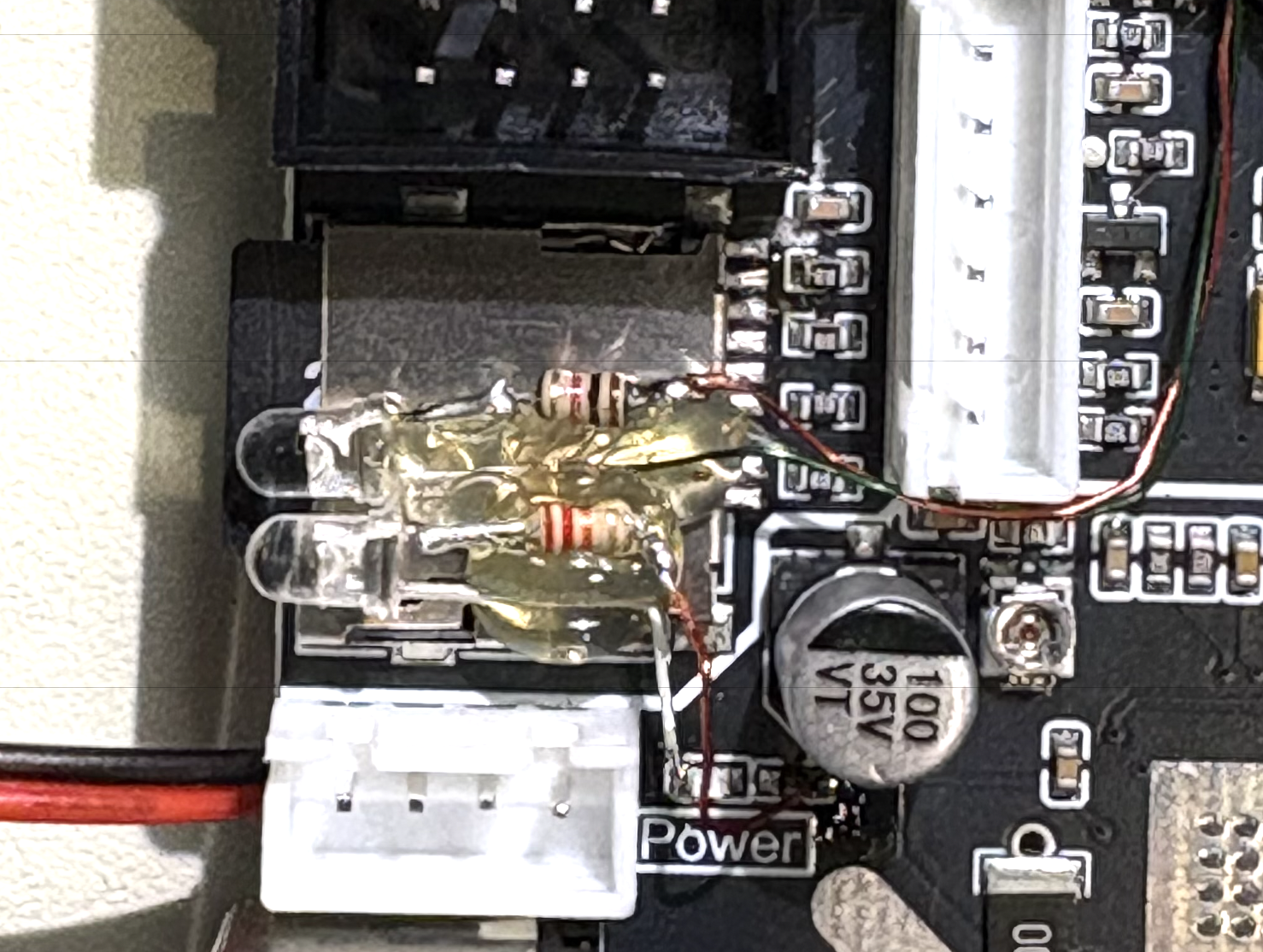
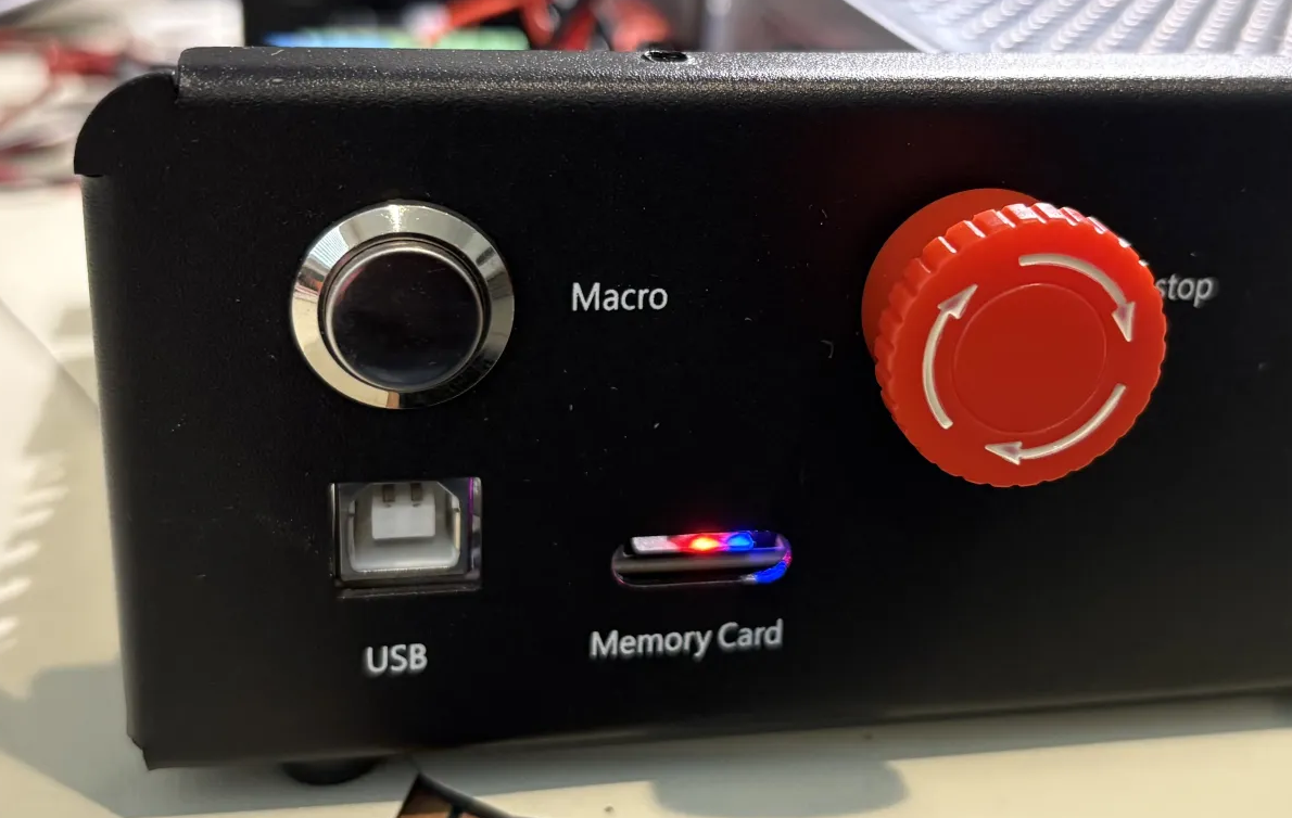
- Power and E-Stop lights: I found it annoying that there was neither a power light nor an indicator that estop had been pressed, so I added a blue power led and a red estop led above the sdcard so they glow through the slot -- I love hot-melt-glue:
- UART for future pendant: I cut a trace to isolate gpio.35 (sd-card-det) to use as a uart rx, and tapped gpio.22 flood_pin (labeled Water) to use as a uart tx, and glued a grove connector above the usb jack, with a couple of pullups. These signals need to go through isolation and cable driving, of course, but I can plug a little board in there later and then get into a pendant build. Tested the port with coolterm.
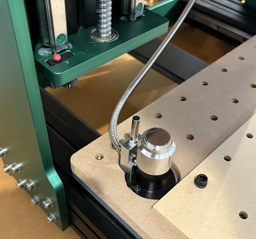
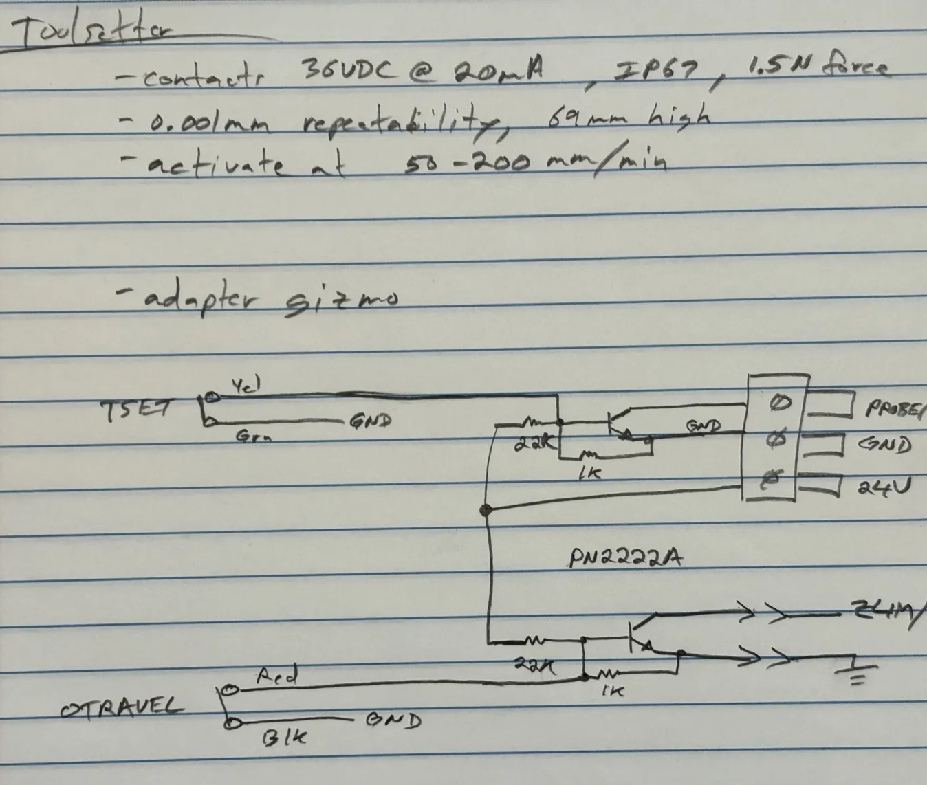
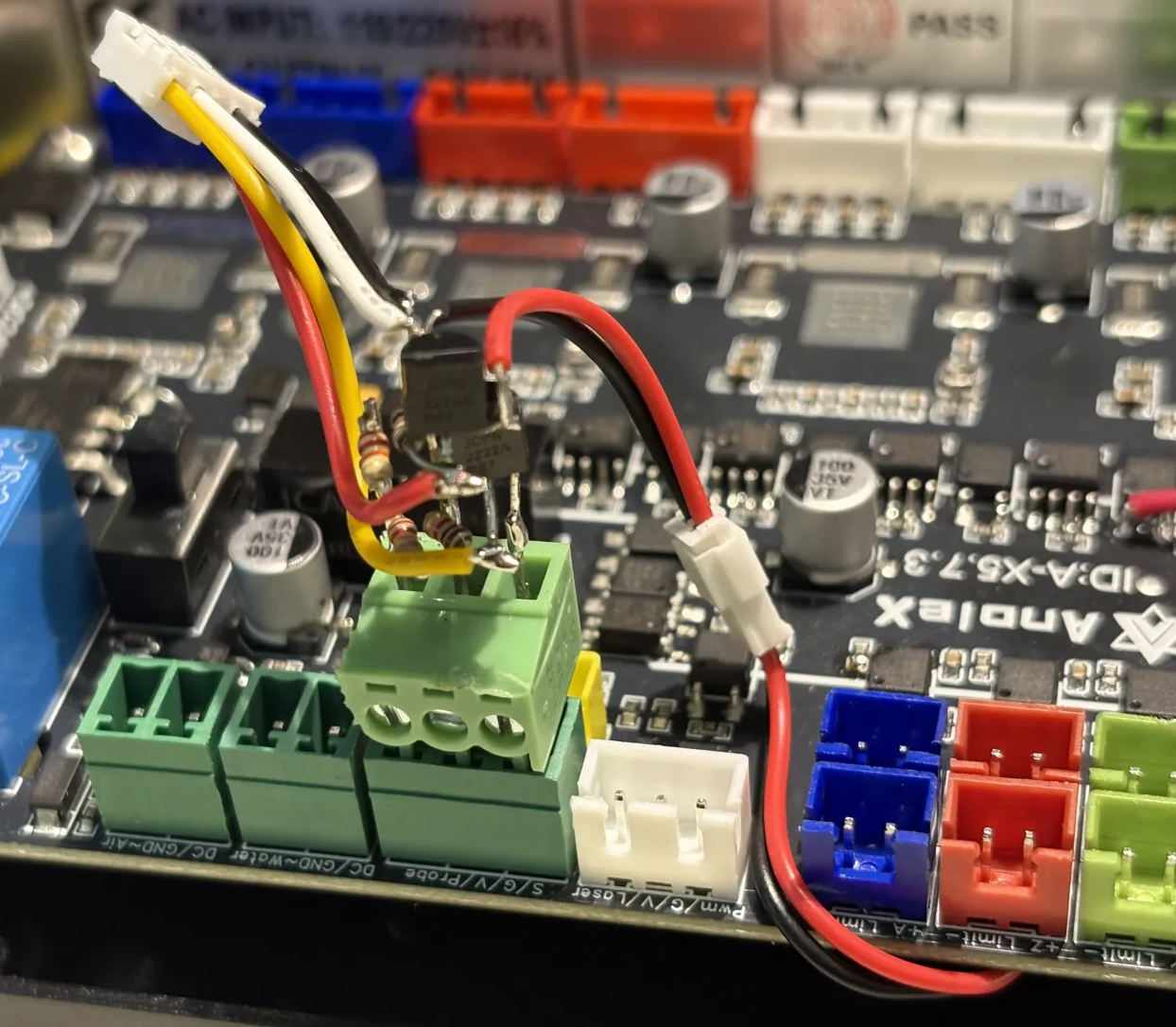
- Added a toolsetter and interface gizmo -- a 3-pin plug circuit with a couple of NPNs and a few resistors, encased in hot melt glue. It converts the N.C. toolsetter switch to drive the N.O. PROBE/ input, and also converts the N.C. overtravel switch to drive the N.O. ZLIM/ input. The probe and toolsetter inputs are logically considered the same in fluidnc. They can be on different pins (and defined separately in the config.yaml), OR they can both be on the SAME pin, in which case only the probe pin needs to be defined. In fact, you will get an error if the yaml specifies both use the same pin. So in this case they are both paralleled on the PROBE/ input.
I am using FreeCAD CAM to generate my gcode, and it has the appropriate M6 commands embedded for tool changes. I have an M6 macro defined in the spindle section of the yaml file linked above.
This is frequently being refined, but here is my current M6 macro file, fwiw: Download macro-m6-tool-change.nc