¶ BigTreeTech Rodent
¶ Overview
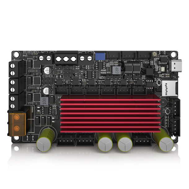
BIGTREETECH Rodent CNC Control Board – FluidNC Compatible, Supports PWM & RS485 Control Modes.
Early versions of the configuration file shown below had
r_sense_ohms: 0.022instead of the correct value0.075. That was due to incorrect information in the Rodent schematic in the Rodent github repo, and in the example config file in that repo. The effect of having the wrong value is to reduce the current by a factor of 3.4, so if you asked for 2 amps of run current, you would actually get about 0.6 amps. The motors would have much less torque than expected. If you use a BTT Rodent, please check your config file to make sure that you haver_sense_ohms: 0.075for all motors.
Between board versions V1.0 and V1.1, BTT changed the pin assignment for the E1 Lim input from GPIO37 to GPIO39. There is still a lot of documentation out there with the wrong information. If you are using that input, you will need to use gpio.39 to refer to it, unless you are one of the few people who have the early V1.0 board.
This wiki page is a work in progress. Please be patient and consider donating to FluidNC. This is just a collection of thing we have learned about the controller as we help users. This is not "official" information. Use at your own risk.
¶ Features
- (4) TMC2160 motor drivers (3A)
- RS485 Interface
- (5) Limit Switch Inputs
- Probe Input
- I2C Interface (0.96 OLED)
- (3) MOSFETs
- (1) Rubber Duck
¶ Where to buy it
¶ Documentation
¶ Support Info
- Github
- BTT email support: service001@biqu3d.com
¶ Input Power
- 24VDC to 56VDC 10A per manual
- 20VDC to 60VDC per silkscreen
¶ Mating Connectors
JST-XH 2.5mm (3 and 4 position)
¶ USB
This uses a USB C connector and a CH340K USB/Serial chip.
Board version 1.0
You can power the ESP32 via USB alone if you install the jumper next to the USB connector. Do not apply main power when this jumper is installed.
Board version 1.1
The v1.1 does not require a USB jumper to use the USB for programming and serial communication. There will not be any LED indicators that the board is operational when using only USB power. It is ok to have main power applied to VCC while programming the v1.1.
If you have trouble with the USB on MacOS see this issue. There is an even newer version of the CH340 driver as described here.
¶ Motor Drivers
There appear to be errors in the schematic and config files regarding the current sense resistors (r_sense_ohms:). Everything says to use 0.022, but it appears that the controller actually has 0.075 ohm sense resistors. The value is used by FluidNC to set the current. This can explain why people are complaining about low motor power. Setting 3 amps would only get you 0.88 amps if you use the wrong value.
The motor drivers a TMC2160 and can be configured up to 3A. Define them as TMC2160 or TMC5160 (compatible). You can define the driver for use with any axis or as a second motor for any axis, like XYZA, XYYZ, etc. The spi_index value in the config file indicates which driver you are configuring. They are numbered 1 through 4, from left to right. FluidNC needs to know that there are 4 motor drivers in the daisy chain. If you are using less than 4, one of the drivers you need to use is number 4.

The motors are labeled X, Y, Z and E. They can actually be used for any axis or motor number in FluidNC as long as you use the I/O associated with each motor.
¶ Switch Input Connectors (SW1-SW5)
Each switch input has 3 pins - switch voltage (SW_VCC - pin 3), ground (GND - pin 2) and signal (pin 1). The input is active when current flows between signal and ground.
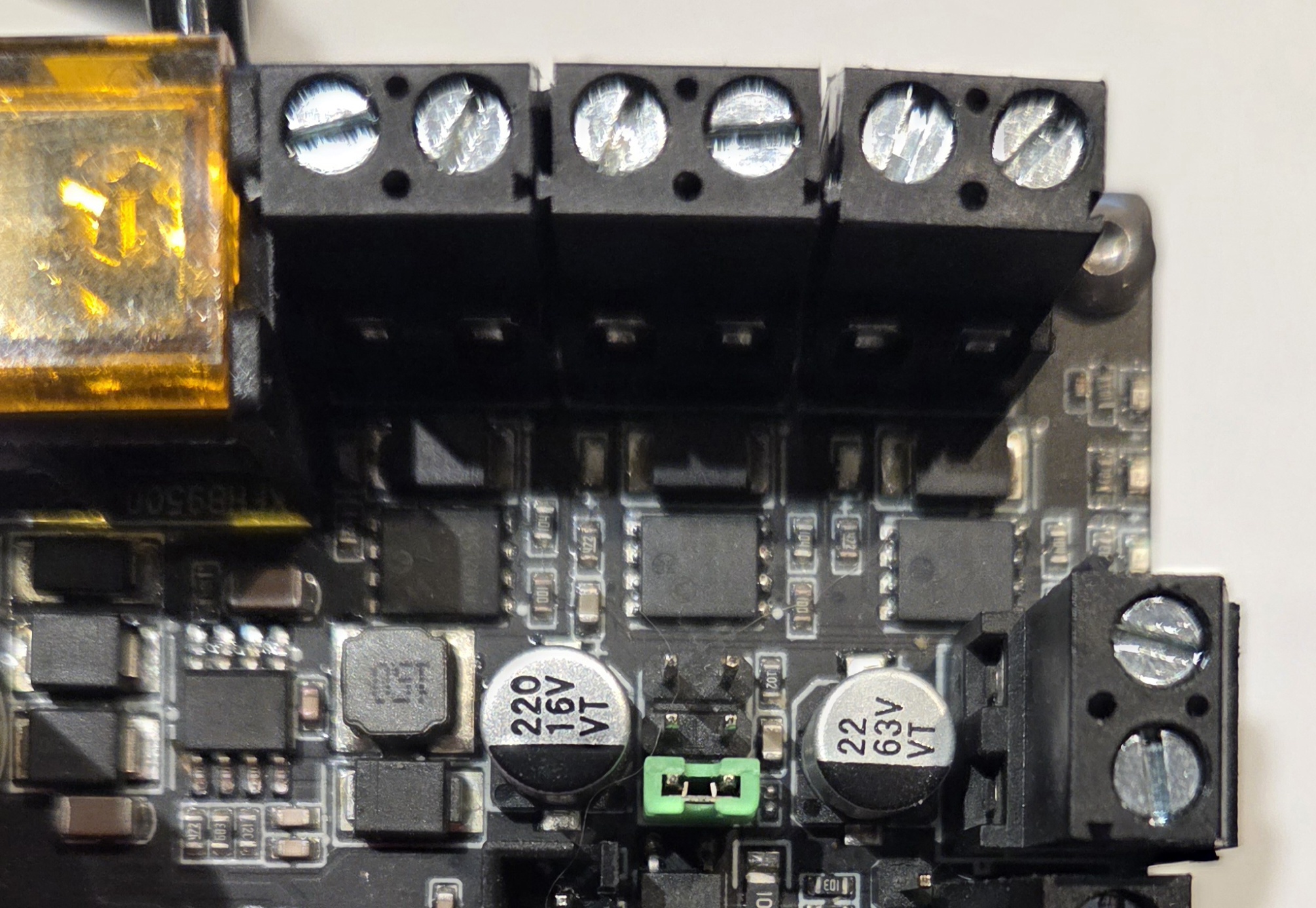
The voltage (5v, 12v and V-Motor) for the switch is selectable via the V-Lim Jumper. If no jumper is installed, the only kind of sensor that will work is one that supplies a voltage output - which is very unlikely.
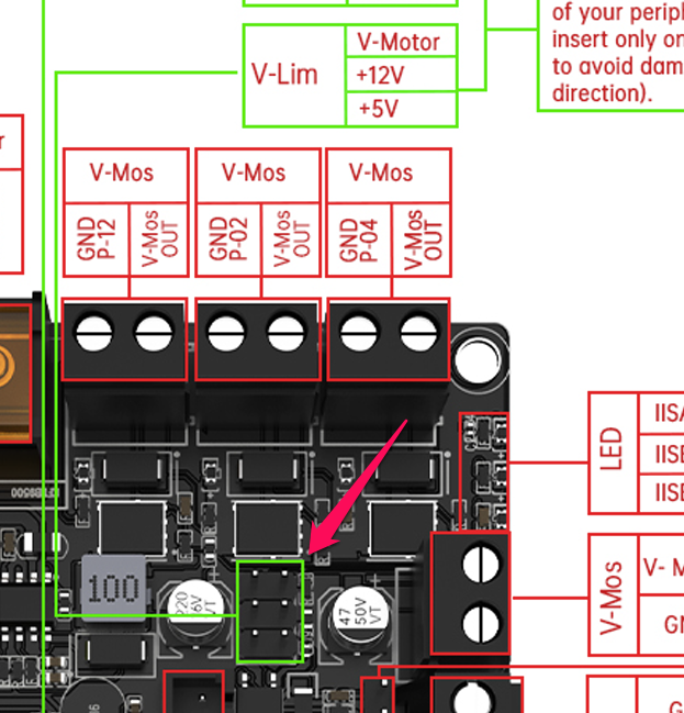
Here is an example of the jumper (green) placed in the position for 5V SW_Vcc
We do not recommend using the VBB position if the input voltage exceeds 24V. At 24V, the resistor in the optocoupler circuit below will dissipate over 500 mW, close to its rating.
If your limit switch is a bare switch, connect it across signal and ground, i.e. pins 1 and 2, and set SW_VCC to 5V (although 12V will also work).
If your limit switch is a 3-pin sensor with voltage, signal, and ground wires, connect voltage to pin 3 (SW-VCC), signal to pin 1, and ground to pin 2. Set SW-VCC to the voltage that your sensor requires.
In your config file, set the low/high modifier according to the switch type. YThe :PU modifier is not necessary.
gpio.34:lowfor a normally open switchgpio.34:highfor a normally closed switch
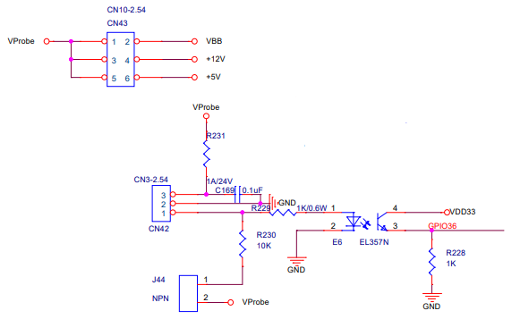
Schematic snippet
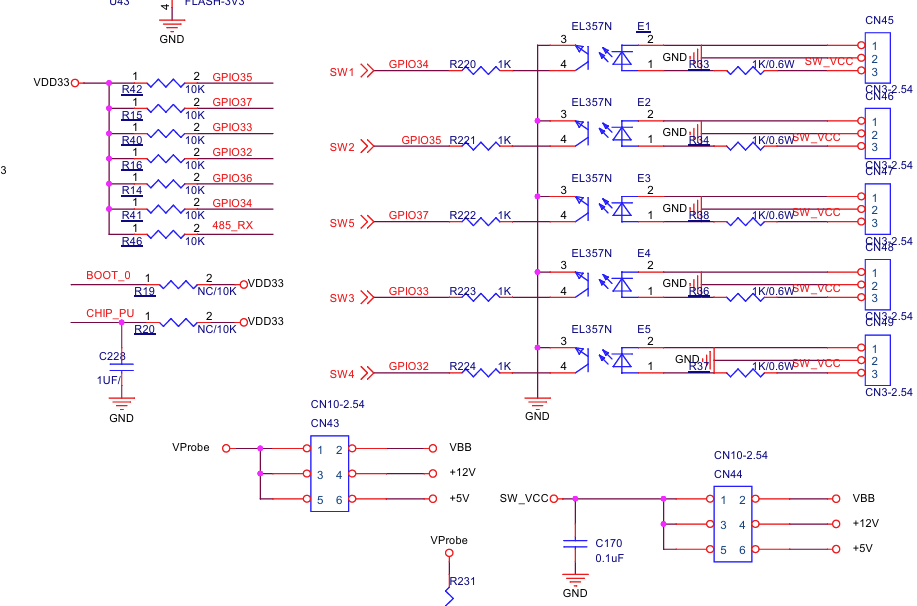
The schematic above shows SW5 on GPIO37. That is only correct for Rodent V1.0. Newer V1.1 boards have that function on GPIO39.
¶ Probe
The voltage (5v, 12v and V-Motor) for the probe is selectable via the V-Probe Jumper (CN43 on the schematic), separate from the voltage for the other switch inputs.
If your probe needs power place one jumper on the probe voltage selector jumpers. The NPN EN jumper can be installed if you want a pull up resistor on the signal pin. This can be used with NPN circuits that float in one state and switch to ground in the other state.
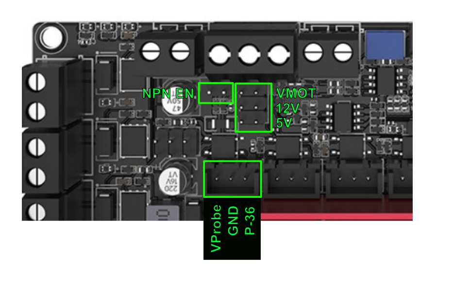
The same voltage selection considerations as described above apply to the probe, albeit to the probe sensor hardware which might be different than your limit switch hardware.
¶ Using stallguard.
Untested: There are jumpers to tie the diag pins to the limit switch inputs. See the back of the controller for the location.
¶ MOSFETs
A MOSFET output is like a switch that conducts current to ground when on, and does not conduct when off. In the on state, a MOSFET can handle quite a few amperes of current depending on the size - typically much more current than a direct MCU GPIO. In the off state, a MOSFET can "stand off" large voltages - many tens of volts - compared to an MCU GPIO's 3.3V or 5V. The Rodent MOSFETs are rated at 11A current and 60V standoff voltage but it would be prudent to restrict their use to perhaps 40V and 5A. They can be used for loads like relays, small pumps, heaters, DC motor and solenoids that require more DC current and voltage than an ordinary digital output can handle. They are somewhat resilient against turn-off spikes from inductive loads like relays and solenoids.
MOSFET outputs are often used with load devices that need a supply voltage like 12V or 24V. That voltage might or might not be the same as the V-Motor voltage that supplies the motor drivers and other circuitry on the Rodent board.
Each Rodent MOSFET output connector has a terminal labeled V-Mos OUT and one labeled GND P-nn. The V-Mos OUT terminals can supply the positive voltage to the "high side" of the load and the GND P-nn terminal is for the "low side" of the load, either conducting current to ground or not. That low-side terminal is poorly named - it is not a true GND connection, but rather a "switch to GND when on". The high-side V-Mos OUT terminals have an on-board connection to the V-Mos IN terminal of the V-MOS power input connector on the long side of the board. If the V-Motor supply voltage is suitable for your load devices, you can connect a wire from V-Motor over to V-Mos IN and let the board's ground plane serve as the GND connection. If your load needs a different voltage, connect the positive side of a suitable power supply to the V-Mos IN terminal and the negative side to the adjacent V-Mos GND terminal.
You could also use an external power connection to the high side of the load, but be sure to wire the low side of that power supply to the V-Mos GND connector. If you use an external connections instead of going through the V-Mos OUT pins, the LED indicators on the MOSFET outputs will not work.
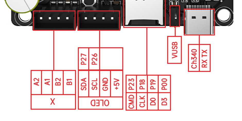
¶ I2C (OLED) Interface
- gpio.26 I2C SCL
- gpio.27 I2C SDA
Uses 10k series resistors on each gpio.
¶ Spindles
¶ PWM
3V - 10V adjustable via potentiometer.
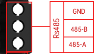
¶ RS485
See back of controller for A and B pins. See this page for more info on RS485
There is an Rx LED to help with diagnostics.
¶ Spindle Digital Signals
The Rodent has three 3-pin JST connectors labeled DIRECTION (GPIO 15), SPINDLE_EN (GPIO 25), and SPINDLE_FB (GPIO 14). GPIOs 14 and 15 are also used for RS485, so those cannot be used if RS485 is in use.
These three signals go directly to ESP32 GPIOs via 100 ohm series resistors, with transient voltage protection on the pins. They could be used as either outputs or inputs for anything that is compatible with 3.3V signaling. They do not work well for direct connection to VFD digital inputs, since such inputs are typically optoisolated with the high side connected to a voltage like 12V or 24V. If you tried to use one of these signals with such a VFD input, it would not be able to turn off properly because the ESP32 GPIO output cannot rise to a high enough voltage to allos the VFD's optocoupler to stop conducting current.
You could work around this problem with an external circuit like an optocoupler, MOSFET module, or relay module (but only the kind of relay module that has an on-board driver transistor; not a bare relay). Or you could connect VFD digital inputs to Rodent MOSFET outputs - connect the VFD COM to any true GND connection on the Rodent, and connect the VFD digital input to one of (poorly named) MOSFET GND Pnn terminals.
They would work for controlling spindle drivers that use low-voltage MCU-compatible signaling.
¶ Config Info
The controller has TMC2160 drivers. FluidNC does not support these by name yet. FluidNC does support TMC5160, which is functionally compatible with TMC2160, so you should specify tmc5160 in the config file. The difference between TMC2160 and TMC5160 is that TMC5160 has a built-in motion controller function that FluidNC does not and cannot use. As far as FluidNC is concerned, the chips behave identically.
Default config file
board: BTT Rodent V1.0
name: BTT CNC
meta: (10.11.2024) by BTT

kinematics:
  Cartesian:

# stepping:
#   engine: RMT
#   idle_ms: 250
#   dir_delay_us: 1
#   pulse_us: 2
#   disable_delay_us: 0
stepping:
  engine: I2S_STREAM
  idle_ms: 255
  pulse_us: 4
  dir_delay_us: 1
  disable_delay_us: 0

axes:
  shared_stepper_disable_pin: NO_PIN
  x:
    steps_per_mm: 800.000
    max_rate_mm_per_min: 5000.000
    acceleration_mm_per_sec2: 100.000
    max_travel_mm: 300.000
    soft_limits: false
    homing:
      cycle: 1
      positive_direction: false
      mpos_mm: 150.000
      feed_mm_per_min: 100.000
      seek_mm_per_min: 200.000
      settle_ms: 500
      seek_scaler: 1.100
      feed_scaler: 1.100

    motor0:
      limit_neg_pin: NO_PIN
      limit_pos_pin: gpio.35
      limit_all_pin: NO_PIN
      hard_limits: false
      pulloff_mm: 1.000
      tmc_5160:
        step_pin: I2SO.2
        direction_pin: I2SO.1
        disable_pin: I2SO.0
        cs_pin: gpio.5
        spi_index: 1
        r_sense_ohms: 0.075
        run_amps: 1.5
        hold_amps: 0.5
        microsteps: 8
        toff_disable: 0
        toff_stealthchop: 5
        use_enable: false
        run_mode: CoolStep
        homing_mode: CoolStep
        stallguard: 16
        stallguard_debug: false
        toff_coolstep: 3
        tpfd: 4

  y:
    steps_per_mm: 800.000
    max_rate_mm_per_min: 5000.000
    acceleration_mm_per_sec2: 100.000
    max_travel_mm: 300.000
    soft_limits: false
    homing:
      cycle: 1
      positive_direction: true
      mpos_mm: 150.000
      feed_mm_per_min: 100.000
      seek_mm_per_min: 200.000
      settle_ms: 500
      seek_scaler: 1.100
      feed_scaler: 1.100

    motor0:
      limit_neg_pin: NO_PIN
      limit_pos_pin: gpio.34
      limit_all_pin: NO_PIN
      hard_limits: false
      pulloff_mm: 1.000
      tmc_5160:
        step_pin: I2SO.5
        direction_pin: I2SO.4
        disable_pin: I2SO.7
        cs_pin: NO_PIN
        spi_index: 2
        r_sense_ohms: 0.075
        run_amps: 1.5
        hold_amps: 0.5
        microsteps: 8
        toff_disable: 0
        toff_stealthchop: 5
        use_enable: false
        run_mode: CoolStep
        homing_mode: CoolStep
        stallguard: 16
        stallguard_debug: false
        toff_coolstep: 3
        tpfd: 4

  z:
    steps_per_mm: 800.000
    max_rate_mm_per_min: 5000.000
    acceleration_mm_per_sec2: 100.000
    max_travel_mm: 300.000
    soft_limits: false
    homing:
      cycle: 1
      positive_direction: true
      mpos_mm: 150.000
      feed_mm_per_min: 100.000
      seek_mm_per_min: 800.000
      settle_ms: 500
      seek_scaler: 1.100
      feed_scaler: 1.100

    motor0:
      limit_neg_pin: NO_PIN
      limit_pos_pin: gpio.33:pu
      limit_all_pin: NO_PIN
      hard_limits: false
      pulloff_mm: 1.000
      tmc_5160:
        step_pin: I2SO.10
        direction_pin: I2SO.9
        disable_pin: I2SO.8
        cs_pin: NO_PIN
        spi_index: 3
        r_sense_ohms: 0.075
        run_amps: 1.5
        hold_amps: 0.5
        microsteps: 8
        toff_disable: 0
        toff_stealthchop: 5
        use_enable: false
        run_mode: CoolStep
        homing_mode: CoolStep
        stallguard: 16
        stallguard_debug: false
        toff_coolstep: 3
        tpfd: 4

  a:
    # E0
    steps_per_mm: 157.750
    max_rate_mm_per_min: 18000.000
    acceleration_mm_per_sec2: 1500.000
    max_travel_mm: 325.000
    soft_limits: true
    homing:
      cycle: 1
      positive_direction: true
      mpos_mm: 150.000
      feed_mm_per_min: 100.000
      seek_mm_per_min: 800.000
      settle_ms: 500
      seek_scaler: 1.100
      feed_scaler: 1.100

    motor0:
      limit_neg_pin: NO_PIN
      limit_pos_pin: gpio.32:pu
      limit_all_pin: NO_PIN
      hard_limits: false
      pulloff_mm: 1.000
      tmc_5160:
        step_pin: I2SO.13
        direction_pin: I2SO.12
        disable_pin: I2SO.15
        cs_pin: NO_PIN
        spi_index: 4
        r_sense_ohms: 0.075
        run_amps: 1.5
        hold_amps: 0.5
        microsteps: 16
        toff_disable: 0
        toff_stealthchop: 5
        use_enable: false
        run_mode: CoolStep
        homing_mode: CoolStep
        stallguard: 16
        stallguard_debug: false
        toff_coolstep: 3
        tpfd: 4

i2so:
  bck_pin: gpio.22
  data_pin: gpio.21
  ws_pin: gpio.17

spi:
  miso_pin: gpio.19
  mosi_pin: gpio.23
  sck_pin: gpio.18

sdcard:
  cs_pin: gpio.0
  card_detect_pin: NO_PIN
  frequency_hz: 8000000

# probe:
#   pin: gpio.36:low


# Begin Huanyang
uart1:
  txd_pin: gpio.15
  rxd_pin: gpio.16
  rts_pin: gpio.14
  baud: 9600
  mode: 8N1

Huanyang:
  uart_num: 1
  modbus_id: 1
  tool_num: 0
  speed_map: 0=0% 0=25% 6000=25% 24000=100%
  off_on_alarm: false

# PWM:
#   pwm_hz: 5000
#   output_pin: gpio.13
#   enable_pin: gpio.25
#   direction_pin: gpio.15
#   disable_with_s0: false
#   s0_with_disable: false
#   spinup_ms: 0
#   spindown_ms: 0
#   tool_num: 0
#   speed_map: 0=0% 10000=100%
#   off_on_alarm: false

i2c0:
   sda_pin: gpio.27
   scl_pin: gpio.26

# oled:
#    i2c_num: 0
#    i2c_address: 60
#    width: 128
#    height: 64
#    radio_delay_ms: 1000

status_outputs:
  report_interval_ms: 500
  idle_pin: I2SO.11:low
  run_pin: I2SO.14:low
  alarm_pin: I2SO.3:low
# hold_pin: gpio.16
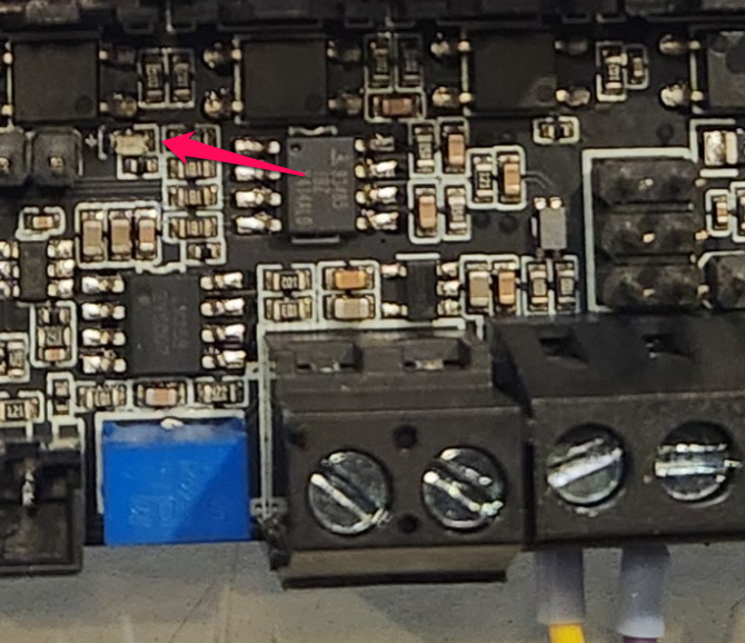
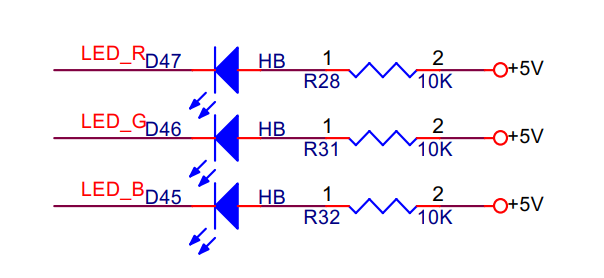
¶ Status LEDs
There are 3 LEDs next along the edge near the MOSFETs
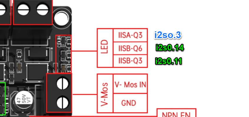
They are all active low. Note: Colors are wrong on schematic
status_outputs:
  report_interval_ms: 500
  idle_pin: I2SO.11:low
  run_pin: I2SO.14:low
  alarm_pin: I2SO.3:low
¶ GPIO Pin Map
- gpio.0 SD Card CS
- gpio.2 MOSFET
- gpio.4 MOSFET
- gpio.5 CS for motor drivers
- gpio.12 MOSFET
- gpio.13 Spindle PWM Output
- gpio.14 RS485 rts
- gpio.15 RS485 txd (and Spindle Direction?)
- gpio.16 RS485 rxd
- gpio.17 I2S WS
- gpio.18 spi SCK
- gpio.19 spi MISO
- gpio.21 I2S Data
- gpio.22 I2S BCK
- gpio.23 spi MOSI
- gpio.25 Spindle Enable
- gpio.26 I2C SCL
- gpio.27 I2C SDA
- gpio.32 E-Lim
- gpio.33 Z-Lim
- gpio.34 Y-Lim (no :pu/:pd)
- gpio.35 X-Lim (no :pu/:pd)
- gpio.36 Probe (no :pu/:pd)
- gpio.37 E1 Lim - Only on board revision 1.0 (no :pu/:pd)
- gpio.38 unknown (no :pu/:pd)
- gpio.39 E1 Lim - On board revision 1.1 (no :pu/:pd)
¶ I2SO Pin Map
- is2o.0 X Disable
- is2o.1 X Dir
- is2o.2 X Step
- is2o.3 LED R
- is2o.4 Y Dir
- is2o.5 Y Step
- is2o.6 Not Used
- is2o.7 Y Enable
- is2o.8 Z disable
- is2o.9 Z Dir
- is2o.10 Z Step
- is2o.11 LED B
- is2o.12 A Dir
- is2o.13 A Step
- is2o.14 LED G
- is2o.15 A Disable