¶ Using the firmware
¶ Compile from the development branch
Use Git to clone the source got and select the S3Async branch and and set default_envs = wifi_s3 in platformio.ini
¶ Bluetooth
The ESP32 supports Bluetooth v4.2 (Classic + BLE), while the ESP32-S3 only supports Bluetooth 5 (LE only).
Bluetooth classic has a SSP (Serial port Profile) feature. This allows you to create a virtual serial port and use serial port programs like gcode senders over Bluetooth without having to modify the sender's code.
SSP is the feature that is currently in FluidNC. Therefore we only support Bluetooth on the ESP32 at this time.
¶ Help, support and feedback
Please use this discord thread.
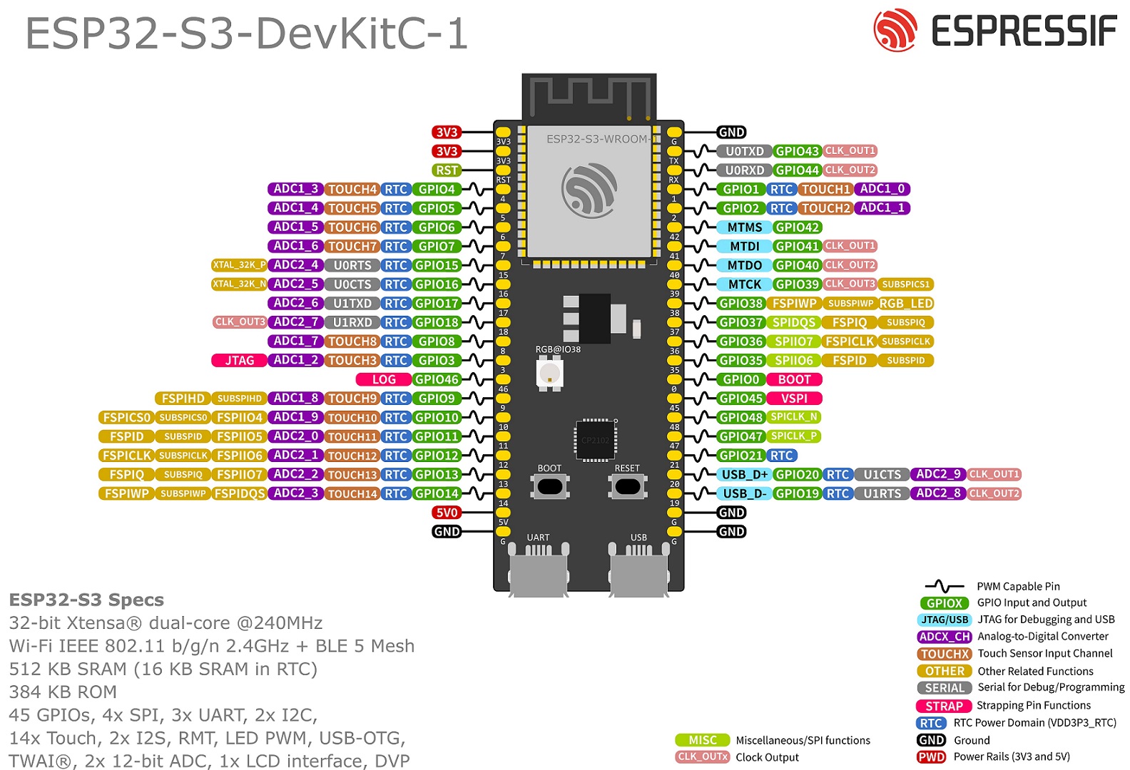
¶ ESP32-S3 Pin Reference
- Espressif user guide
- Schematic
- ESP32-S3-WROOM-1 Datasheet (Module)
- ESP32-S3 Family Datasheet
- ESP32-S3 Technical Reference Manual
- ESP32 S3 Family Pins

This is incomplete and just a collection point for information as it is collected.
¶ Part Numbering
-1and-1UThis indicates the antenna type-1has an PCB antenna-1Uhas an external antenna connector
Nx, Rx, HxNxis the SPI Flash sizeRxis the PSRAM sizeHxis an extended temp FLASH version
¶ Examples:
- ESP32-S3-WROOM-1-N8 PCB antenna with 8M Flash
- ESP32-S3-WROOM-1U-N8R8 External antenns connector, 8M FLASH, 8M PSRAM
¶ Usable I/O pins
- gpio.0 (See strapping pins)
- gpio.1
- gpio.2
- gpio.3 (See strapping pins)
- gpio.4 Weak pull up on reset
- gpio.5
- gpio.6
- gpio.7
- gpio.8
- gpio.9
- gpio.10
- gpio.11
- gpio.12
- gpio.13
- gpio.14
- gpio.15
- gpio.16
- gpio.17
- gpio.18
- gpio.19 Used for native USB D-
- gpio.20 Used for native USB D+
- gpio.21 (See USB OTG Boot Mode)
- gpio.35 Used for PSRAM, weak pull up on reset
- gpio.36 Used for PSRAM
- gpio.37 Used for PSRAM
- gpio.38 (See USB OTG Boot Mode)
- gpio.39 (See USB OTG Boot Mode)
- gpio.40 (See USB OTG Boot Mode)
- gpio.41 (See USB OTG Boot Mode)
- gpio.42 (See USB OTG Boot Mode)
- gpio.45 (See strapping pins)
- gpio.46 (See strapping pins)
- gpio.47 (See USB OTG Boot Mode)
- gpio.48
¶ Do Not Use (generally)
- gpio.19 Used for native USB D-
- gpio.20 Used for native USB D+
- gpio.43 Used for USB/Serial U0TXD
- gpio.44 Used for USB Serial U0RXD
If you have PSRAM, you also cannot use gpio.35 - gpio.37 .
¶ USB Options
¶ USB/Serial
Most controllers and dev modules will use this as the primary programming and console. This is the safest method to use and can assist with boot details and backtraces.
¶ Native CDC USB
The S3 chip has internal support for a USB using CDC. The plan is to be able to use this. It could be used as a normal USB/Serial connection or possibly for devices like joystick, etc. To use this you should compile from source to get the latest code.
¶ Strapping Pins
Typically these can be used, but you need to make sure they are not in the wrong state during boot.
- gpio.0 Boot Mode. Weak pullup during reset. (Boot Mode 0=Boot from Flash, 1=Download)
- gpio.3 JTAG Mode. Weak pull down during reset. (JTAG Config)
- gpio.45 SPI Flash voltage. Weak pull down during reset. (SPI Voltage 0=3.3v 1=1.8v)
- gpio.46 Boot mode. Weak pull down during reset. (Enabling/Disabling ROM Messages Print During Booting)
While not recommended, it is possible to burn the SPI voltage in a EFuse, effectively ignoring gpio.45. See Espressif EFuse docs for more information; look for VDD_SPI .
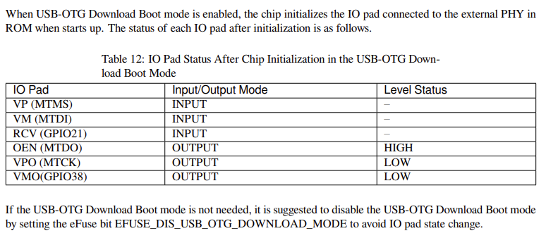
¶ USB-OTG Download Boot Mode
These pins are set as shown below
VP (MTMS) (GPIO42)
VM (MTDI) (GPIO47)
RCV (GPIO21)
OEN (MTDO) (GPIO40) Output High
VPO (MTCK) (GPIO39) Output LOw
VMO (GPIO38) Output Low

¶ Default Pins
These pins are the default pins, however they can be remapped to any other gpio.
¶ I2C
Default pins in the Arduino framework are:
- gpio.9 SCL
- gpio.8 SDA
I2C can be mapped to any available gpio pin without a penalty.
There is an aditional I2C interface which does not seem to have default pins.
¶ SPI
The ESP32 S3 has four SPI interfaces which are:
- SPI0 used by ESP32-S3’s cache and Crypto DMA (EDMA) to access in-package or off-package flash/PSRAM
- SPI1 used by the CPU to access in-package or off-package flash/PSRAM
- SPI2 is a general purpose SPI controller with its own DMA channel
- SPI3 is a general purpose SPI controller with access to a DMA channel shared between several peripherals
The SPI2 (VSPI) default pins are:
- gpio.12 SCK Defined as SPI0_SCK
- gpio.11 MOSI Defined as SPI0_MOSI
- gpio.13 MISO Defined as SPI0_MISO
- gpio.10 CSO Defined as SPI_CS0
These default pins run through the IOMUX instead of the GPIO matrix, and therefore have higher
performance characteristics. The maximum frequency for IOMUX pins is 80 MHz.
SPI3 does not have default pin mappings because it can be mapped to any available gpio pins.
¶ I2S
The ESP32 S3 has two I2S interfaces which can be mapped to any available gpio pins.