¶ ESP32 Pin Reference
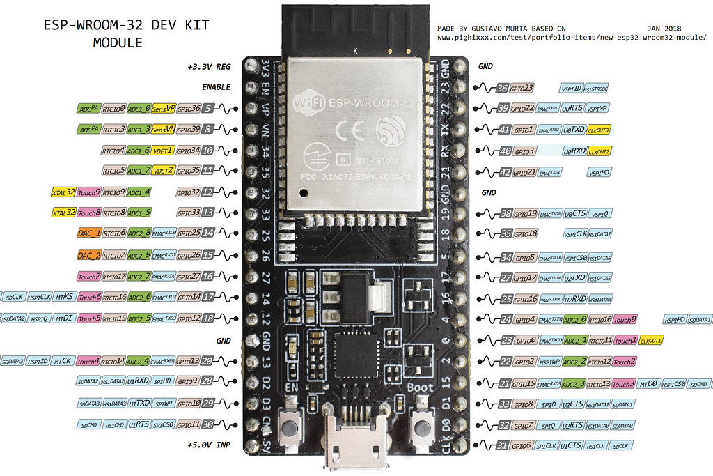
Here is a pinout for an ESP32 Dev Kit (ESP32-DevKitC V4). This is common module used for FluidNC controllers, but other versions will work on controllers designed for them. This is a good reference of the capabilities of each pin.
Try to buy from a reputable seller. The best come from Espressif and cost about $10. You can find them from AliExpress, for cheaper, but these often have low quality compenets and have trouble programming or crash often due to power issues.
Be sure to use the WROOM version and not the WROVER version. The WROVER uses PSRAM and that uses up some GPIO.
They are available with different RAM sizes. FluidNC uses the 4MB size. Getting a larger size will not be of much benefit. The web installer and release packages will format it as 4MB by default, so the extra FLASH is not available. Advanced programmers only: If you know how to compile and how to use alternate partition sizes, you can allocate the extra flash for the local file sytem.
See the end of the doc for other types.


¶ Usable I/O pins
- GPIO_NUM_0 - This is used for the bootloader (Usable, but for experts only). If it is low on boot it will enter bootloader mode. It is best if you can guarantee that it is high regardless of the connected item state at boot. For example if you use it for a limit switch, the switch could force a low state and cause problems.
- GPIO_NUM_2
- Some dev boards have an LED on this. It does not work well as an input if this is the case because the LED affects the voltage on the pin.
- It is a strapping pin. It must be either left unconnected/floating, or driven Low, in order to enter the serial bootloader (read more)
- It works well as the spindle pin. The LED gives a nice indication of the spindle on and PWM level.
- GPIO_NUM_4
- GPIO_NUM_5
- GPIO_NUM_12
- It is a strapping pin. If driven High, flash voltage (VDD_SDIO) is 1.8V not the default 3.3V. This pin has an internal pull-down resistor, so unconnected = Low = 3.3V. If driven high, the flash may brownout. If however the flash is meant to work at 1.8V then not driving this pin to High may cause the flash to burn out (read more). Most off the shelf controlers (such as the the ESP-WROOM-32) work at the default 3.3V
- You can remove the strapping pin feature by setting the one time programmable efuse.
python espefuse.py --port COM4 set_flash_voltage 3.3V. This will prevent the pin from being checked.
- GPIO_NUM_13
- GPIO_NUM_14 (some pulses at boot)
- GPIO_NUM_15
- Some pulses at boot
- It is a strapping pin. If driven Low, silences boot messages printed by the ROM bootloader. Has an internal pull-up, so unconnected = High = normal output (read more).
- GPIO_NUM_16
- GPIO_NUM_17
- GPIO_NUM_18
- GPIO_NUM_19
- GPIO_NUM_21
- GPIO_NUM_22
- GPIO_NUM_23
- GPIO_NUM_25
- GPIO_NUM_26
- GPIO_NUM_27
- GPIO_NUM_32
- GPIO_NUM_33
¶ Input Only (no pullup/pulldown)
If you do not have external pull up or pull down resistors. Do not use these pins! We recommend a 5k to 10k resistor. If you don't know how to use pull resistors, google it for some nice pictures and diagrams.
- GPIO_NUM_34
- GPIO_NUM_35
- GPIO_NUM_36
- GPIO_NUM_37 (not typically available)
- GPIO_NUM_38 (not typically available)
- GPIO_NUM_39
¶ Do not use (or not recommended)
- GPIO_NUM_1 - Used for USB/Serial Data
- GPIO_NUM_3 - Used for USB/Serial Data
- GPIO_NUM_20 - This is not available on ESP32
- GPIO_NUM_24 - This is not available on ESP32
- GPIO_NUM_28 - This is not available on ESP32
- GPIO_NUM_29 - This is not available on ESP32
- GPIO_NUM_30 - This is not available on ESP32
- GPIO_NUM_31 - This is not available on ESP32
¶ Unusable GPIO
- GPIO_NUM_6 - Use for External Flash
- GPIO_NUM_7 - Use for External Flash
- GPIO_NUM_8 - Use for External Flash
- GPIO_NUM_9 - Use for External Flash
- GPIO_NUM_10 - Use for External Flash
- GPIO_NUM_11 - Use for External Flash
¶ Default Pin
Some pins have default uses in FluidNC. If you are using these functions, it is best to use the default pins. They have been tested a lot and we know they work.
- I2S
- bck_pin: gpio.22
- data_pin: gpio.21
- ws_pin: gpio.17
- SPI (SD CArd, etc)
- miso_pin: gpio.19
- mosi_pin: gpio.23
- sck_pin: gpio.18
- I2C OLED
- SCL gpio.12
- SDA gpio.15
¶ Other common modules.


