¶ STM32 IO Extender
¶ Overview
This will use the UART channel protocol proposed here. The goal is to define the IO on the chip so everyone can use the same firmware. All available IO on the STM32F103 will be assigned to functions. Most users will only use a subset of the IO.
Ther STM32F103 was chosen because it is easily avialable in the Blue Pill module and cheap on JLCPCB assembly.
The pin assignment were chosen to assign the appropiate pins to the functions.
Schematic (I think)

¶ I/O
¶ FluidNC Channel UART
- PA2 (TX2)
- PA3 (RX2)
¶ Input or Outputs
pin_t pins[] = {
    //           port num  can_PWM?   io_num
    { .gpio = { GPIOA,  4, false } }, //   0
    { .gpio = { GPIOA,  5, false } }, //   1
    { .gpio = { GPIOA,  8, true  } }, //   2
    { .gpio = { GPIOA, 11, false } }, //   3
    { .gpio = { GPIOA, 12, false } }, //   4
    { .gpio = { GPIOB,  6, true  } }, //   5
    { .gpio = { GPIOB,  7, true  } }, //   6
    { .gpio = { GPIOB,  8, true  } }, //   7
    { .gpio = { GPIOB,  9, true  } }, //   8
    { .gpio = { GPIOB, 10, false } }, //   9
    { .gpio = { GPIOB, 11, false } }, //  10
    { .gpio = { GPIOB, 14, false } }, //  11
    { .gpio = { GPIOB, 15, false } }, //  12
    { .gpio = { GPIOC, 13, false } }, //  13
    { .gpio = { GPIOA,  0, true  } }, //  14
    { .gpio = { GPIOA,  1, true  } }, //  15
    { .gpio = { GPIOA,  6, true  } }, //  16
    { .gpio = { GPIOA,  7, true  } }, //  17
    { .gpio = { GPIOB,  0, true  } }, //  18
    { .gpio = { GPIOB,  1, true  } }, //  19
};
¶ Display
These pins are not accessible to FluidNC.
- UART for Pendants
- PA2 (TX2)
- PA3 (RX2)
¶ USB (on BluePill)
- USB- PB12
- USB+ PB13
¶ 6 Pack Module
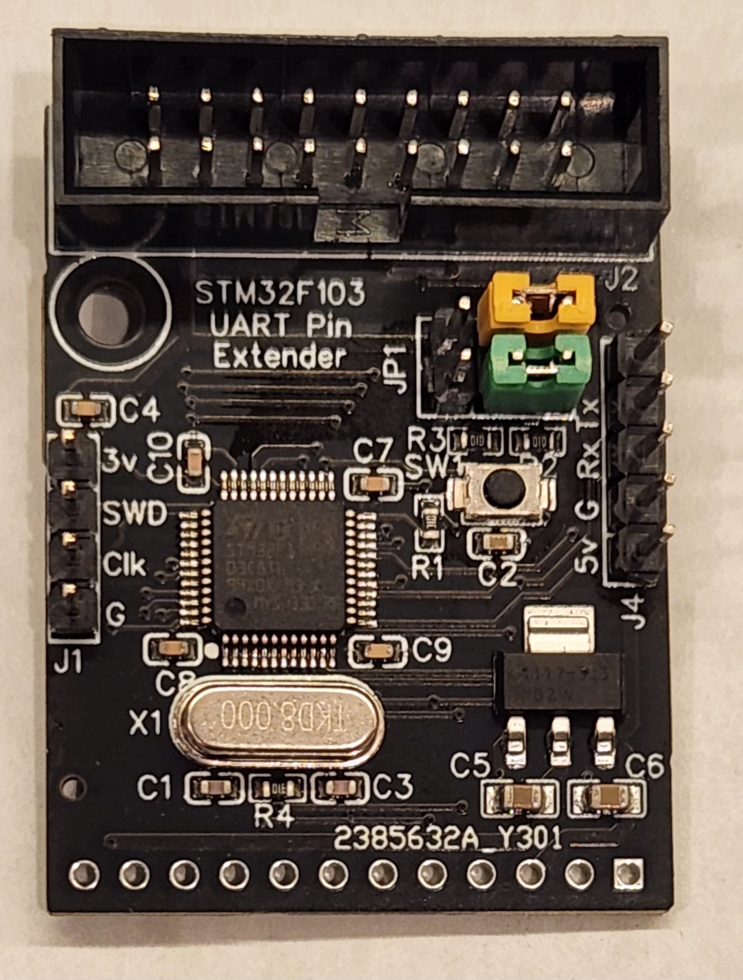
There is a 6 Pack module that is currently being used to develop the UART Channel I/O exansion feature.
Features
- (16) I/O pins. Some can do PWM
- Pass through UART for pendant connection
- ST Link programming header.
- Jumpers for program/run. (it programs for me in run position...show above)
¶ Programming
- Firmware is here.
- Retrieve the firmware using GIT.
- Open the STM32_Expander folder in VSCode
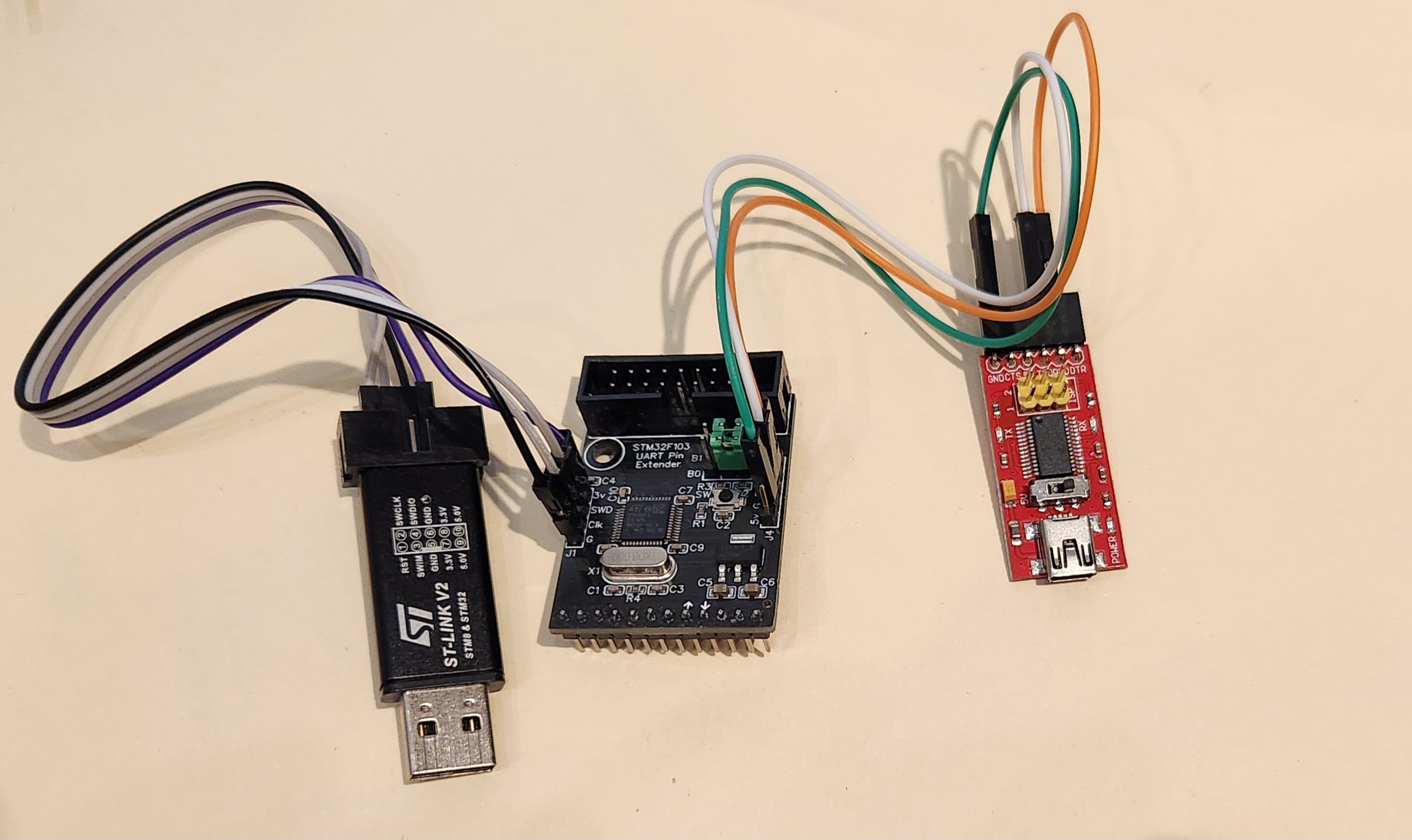
- Plug in aqn ST-Link V2 programmer. Wire 1:1 to 3v, SWD, Clk and GND.
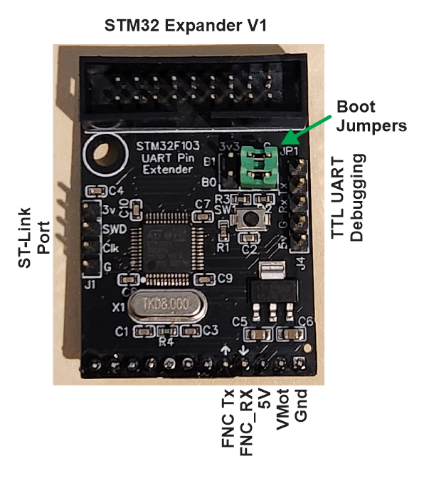
- Place both boot jumpers on the G side. They can stay one that side.
- Click the upload button in vscode.
- Click the reset button or power cycle to run the program.
- Connect a TTL USB/Serial adapter if you want to see debugging text.
Search the internet if you have trouble with the ST-Link USB driver.
¶ Example Config
Module Socket #3
uart1:
  txd_pin: gpio.4
  rxd_pin: gpio.26
  baud: 921600
  mode: 8N1

uart_channel1:
  report_interval_ms: 75
  uart_num: 1
  message_level: None
Module Socket #4
uart1:
  txd_pin: gpio.14
  rxd_pin: gpio.13
  baud: 921600
  mode: 8N1

uart_channel1:
  report_interval_ms: 75
  uart_num: 1
  message_level: None
¶ Version 1
¶ RJ12 Version
¶ Description
This one connects to the FluidNC via RJ12 (or header conn). It has UART to UART pass through, so you can connect a pendant.
- (8) Inputs (Close to ground to activate)
- (8) 5v outputs (digital or PWM) (max 25mA per and 70mA total per terminal block)
- (2) NPN MOSFETs (10A max total for both)
¶ Connecting to the controller.
RJ12
Connect with an RJ12 cable to a RJ12 CNC I/O module on controllers that support that.
Header
Above the RJ12 connector is a simple header with all the signals.
- Be careful with connections. Wiring mistakes can break the expander and controller.
- Keep the cable short. Noise and spikes on the wires can cause errors and damage
- All signals are 3.3v
¶ Configuration
¶ Programming
¶ Via ST-Link

¶ Via FluidNC serial passthrough.
You can use FluidTerm to program the STM32 via the serial bootloader.
Enter bootloader mode
Hold the boot button, press the reset button then release boot button.
There is also boot jumper that can be installed. To use this, install the jumper then press the reset button. To return to normal boot mode, remove the jumper and press reset.
Follow the instructions here to upload the firmware via FluidTerm.
¶ PWM Restrictions
The STM32 uses 4 timers for PWM. These are assigned to the pins in hardware. This means pins that share timers must use the same frequency.
If you try to assign different frequencies for pins that share a timer in the config file, this will happen....(tbd)
¶ Changes to consider on next version
- pulldown resostors on 5V outputs. Undefined pins are floating and allow outputs to chatter. MOSFETs already have them.
- LEDs on the inputs.
- Power LED
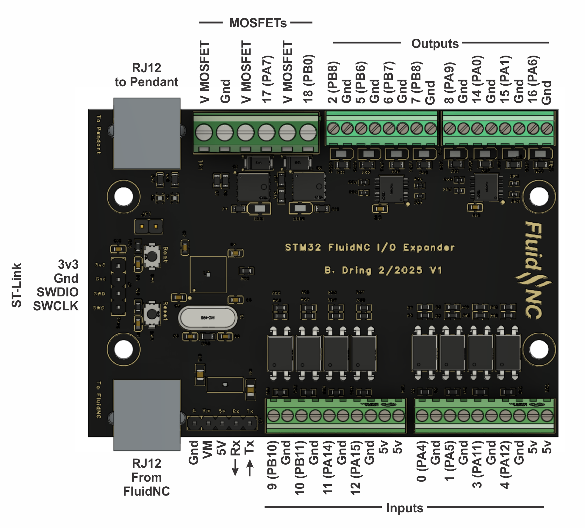
¶ Pinout
The i/o is labeled with the FluidNC number and the STM32 port info, like 2 (PB8). Where 2 is the value used in FluidNC.