¶ ESP32
The ESP32 must be the dual core 240MHz version (ESP32-S1). Versions such as the ESP32-S2, ESP32-C3 are not supported. Any memory size above 4Meg will work. Currently the pre-compiled version will only use 4Meg. The rest of the memory will not be accessible unless you compile yourself with a custom partition. Ask on discord about this.
¶ ESP32-S3
We do not support that new chip yet. The libraries we use do not support it. We want to support it as soon as possible.
¶ Module vs. Devkit.
The DevKit mounted in a socket is recommended for first time controller designers. It is cheap and easy to replace. The module is complicated and very layout sensitive.
¶ Module layout guidelines
Typically the antenna should hang over the edge of the board. If it must be on the PCB be sure there is no copper under the antenna section by as wide a margin as possible.
The USB connections (D- and D+) to the USB/Serial chip should be as short as possible and equal lengths.
¶ Antennas
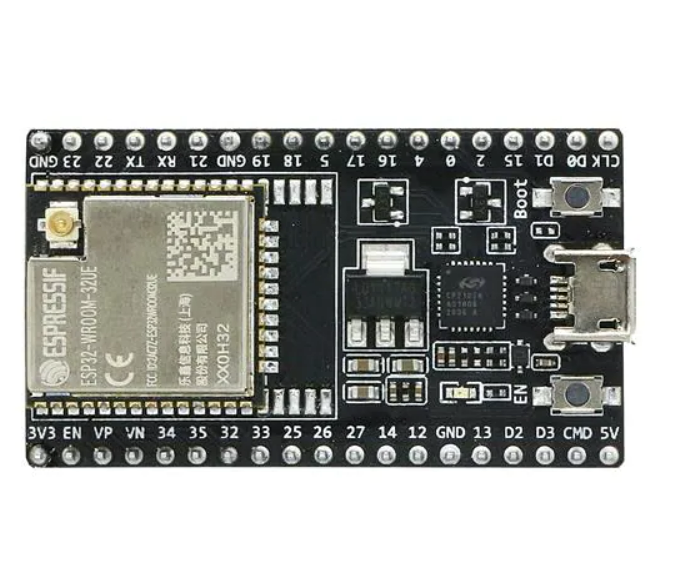
The built in PCB antenna of standard modules is generally good enough. If you need more range, you can get a module with an antenna. The modules typically have a "U" in the part number, like ESP32-DevKitC-32UE.
The antenna connector is usually an IPEX type. You need an adapter cable to something larger like an SMA connector for the antenna.

If you are using Wifi or Bluetooth on a module with an antenna connection, you should only operate when the antenna is connected. This can cause the device to overheat.
¶ Circuit
¶ 5V
Be careful that the USB 5V is not overloaded. Consider a diode that allows the main 5V to power the ESP32, but the USB cannot power the rest of the controller.
The ESP32 can pull spikes of current when turning on the radios. Be sure to add some capacitance on the 5V or 3.3V near the ESP32.
¶ 3.3V
If you are using the 3.3V from the DevKit, be careful not to overload it. It comes from a 3.3V LDO. Only use a few milliamps for things like pullups. If you need more, you should use a separate source.
¶ GPIO Pins
Be sure to check these pin guidelines before starting. It is everything we know about the ESP32. There are other issues, so check ESP32 documentation too. Pay special attention to the turn on conditions of the pins. An external pullup on the wrong pin can prevent proper booting or damage the ESP32.
Create a chart of all the functions you want and map them to the pins.
Try to protect the pins from user mistakes and abuse. For example: If you have an input circuit for a switch, consider what happens if a user accidentally uses that pin as an ouptut and an attached switch creates a short. A simple resistor can be used to limit the current to a safe level for the ESP32.
¶ I2SO Chips
The firmware is designed for 74AHCT595 chips. The "T" is important if you want TTL compatibility. The AHCT595 were chosen for the following reasons:
'595 instead of '194 because the former has holding registers after the shift registers. Without holding registers, as data is being shifted in, each output will cycle through the bits for all of the channels. That will not work at all. With holding registers, the shifted-in data is transferred to the holding register once during the N-bit shift cycle, so the final outputs see only the bits for their respective channels.
AHCT because we wanted to be able to use optocoupled external stepper drivers at 5V drive. You can usually drive their optocouplers at 3.3V but in some cases it is not really in spec and you might have to run a little slower to make them work. With HC logic, the input threshold scales with the supply voltage and Vin high is usually 0.7 x VDD, At 5V VDD, the high input thresholds is 3.5V, higher than the 3V3 outputs from the ESP32. With AHCT logic, the input threshold also scales with VDD, but the transistors are asymmetric so the threshold is lower. 3V3 ESP32 outputs can drive ACHT high with no problems. ACHT chips are not specified for use at 3V3 supply, but that does not mean that they will not work; it just means that their purpose is for use with other 5V logic so the manufacturers do not bother to qualify at 3V3. The only circuit difference between HC and AHCT logic is the input threshold adjustment.
If you use AHC at 3V3 supply:
- The ESP32 will drive it, no questions asked.
- The outputs will definitely drive stepsticks and other on-board stepper driver chips
- The outputs will probably drive external stepper drivers but some might not meet worst case specs (or you could use external buffers)
The I2S engine in the ESP32 can send either 16 bit frames or 32 bit frames. If the total number of shift register bits matches the frame size, the bits will exactly fill the shift registers. If there are more shift register bits than the frame size, the extra SR bits at the end will get old data from the previous frame. If there are fewer SR bits than the frame size, the extra bits in the frame will be shifted out into nowhere. This means you can use 1 to 4 chips.
If you use AHC at 5V supply
- The ESP32 might drive it sometimes, but the noise margin, timing, and reliability will be degraded
- The outputs will drive both stepsticks (with Vdd at 5V) and external drivers within spec
HC/HCT vs AHC/AHCT
AHC/AHCT is about 5x faster than HC/HCT. AHC/AHCT will work at the fastest I2S clock that FluidNC supports, corresponding to min_pulse_us=1. That clock rate allows up to 500K pulses/sec. HC/HCT works only up to min_pulse_us=2, maxing out at 250 pulses/sec.
Startup States
I have not found good documentation on this, but often I seen outputs turn on while the firmware boots. This is typically fraction of a second. A pull down on the I2S_BCK line appears to help but is not foolproof. Be careful about what you control with this outputs. Once established the output pins appear remain stable as long as power is on. They appear to not change if the ESP32 is rebooted.
The chip also has OE (output enable) and MR (reset) pins that can be used by controller designers via timing circuits or direct ESP32 control keep pins off until the Firmware takes over.
¶ Typical I2SO Circuit
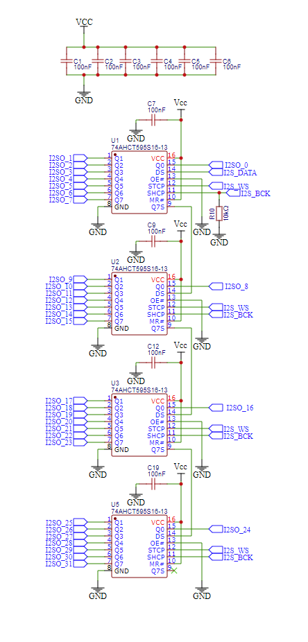
¶ Voltage Level Shifters (ESP32 3.3V to 5V Output)
We generally do not recommend simple level shifters that use pullup resistors for the 5V (like the TI TXS series or MOSFET based ones) - especially not the bidirectional ones. Novices seem to think that they will magically translate between voltage domains, no questions asked - and the product descriptions from vendors like SparkFun reinforce that misconception. In reality, they have problems with speed and ability to supply current. They are useful only in very specific circumstances that rarely occur in CNC controller designs. Many things you are interfacing might have tight timing requirements or might require a few milliamps to work properly. There may be LEDs or pull down resistors in the circuit. See this comprehensive analysis of level shifting techniques.
Here are a few (unidirectional, not bidirectional) chips that are good for to converting ESP32 3.3v outputs to 5V outputs. They can supply enough current to drive the optocoupled inputs of external stepper drivers in many cases.
- 74ACT245 (8 channel) - 25 mA per output, total device limit of 75 mA
- 75HCT125 (4 channel) - 35 mA per out, total device limit of 70 mA
¶ Inputs
¶ Voltage
The ESP32 is a 3.3V part. Do not input 5V to the gpio or it will eventually break.
¶ Pulling Resistors
When using mechanical switches you need to force the circuit into a known voltage state when the switch is open. Otherwise the the input will float. This means it could be at any voltage and FluidNC will not know the true state of the switch. This is typically done with pull up resistors.
Pins 36 through 39 do not have internal pull up or pull down capability. You should add them to your controller. The internal pulling resistors, where they do exist. are quite high, usually around 30k-60k ohm. You may want to add 5k-10k of additional external pullups. (carefully: See pin details)
¶ Electrical debouncing, noise and spikes
There is no firmware debouncing at this time. Controllers should have have circuits to mitigate noise on all inputs. A simple R/C filter usually does it, but adding Schmitt triggers or optos can help as well.
If you use switches that close to ground in a normally closed (N.C.) arrangement that can be more robust to noise. The connection to ground will have a much lower impedance than a pull up and the noise will have a harder time affecting the signal. A normally closed closed limit switch is also fail safe. A break in the circuit will immediately be noticed with hard limits or before a homing attempt.
¶ RC Filtering
An RC (Resistor/Capacitor) filter is also known as a low pass filter. This means it only passes slower voltage changes to the processor. This will remove fast changing noise and switch bounces. You can calculate the time constant (the time that it takes to charge or discharge a capacitor to about 2/3 of its final voltage) of the filter with T = R * C. In this circuit, when the switch opens, the capacitor charges from 3.3V through the series combination of two resistors 10000 (10k) + 1000, so the effective resistance is 11000 ohms, giving 11000R * 0.000001F = 0.011 seconds (11 milliseconds). When the switch is closed, the capacitor discharges to GND very quickly through the switch, bypassing the resistors. A time constant of 0.0001 to 0.015 is usually good. The 1000R resistor is not strictly necessary, but can help protect the ESP32 in the fault case where noise picked up by the external switch wiring drives the input voltage somewhat outside the 0-3.3V range.
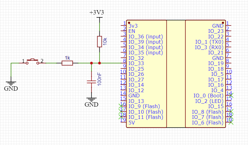
¶ Switch Inputs
If you want to support active switches, consider providing a proper voltage for them. Make sure that the output voltage from the switch is compatible with the 3.3V of the ESP32. If it outputs a higher voltage, you will need to have a level shifter. Some active circuit switches act like NPN transitors and switch to ground. Those can be used if the pullup is 3.3V. The internal ESP32 pullups can typically be used.
¶ Outputs
¶ Connection Labeling
Rather than labeling things like output 1 or mist, consider using the actual IO pin number.
Consider labeling axes as motor numbers. You don't know if someone will use them XYZA or XYYZ
¶ TMC2209 Modules
Most stepstick format modules designed for UART use assume there is a separate UART for each module. They have a pull down resistor on the PDN_UART (Powerdown and UART) pin. If you put all modules on the same UART, you will probably need to remove the resistors. See this thread.
¶ Displays, Pendants and I/O Expanders
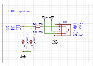
We do not recommend i2c displays for new designs. All future work will be done via UART channels.
We recomend the use of an RJ12 socket.
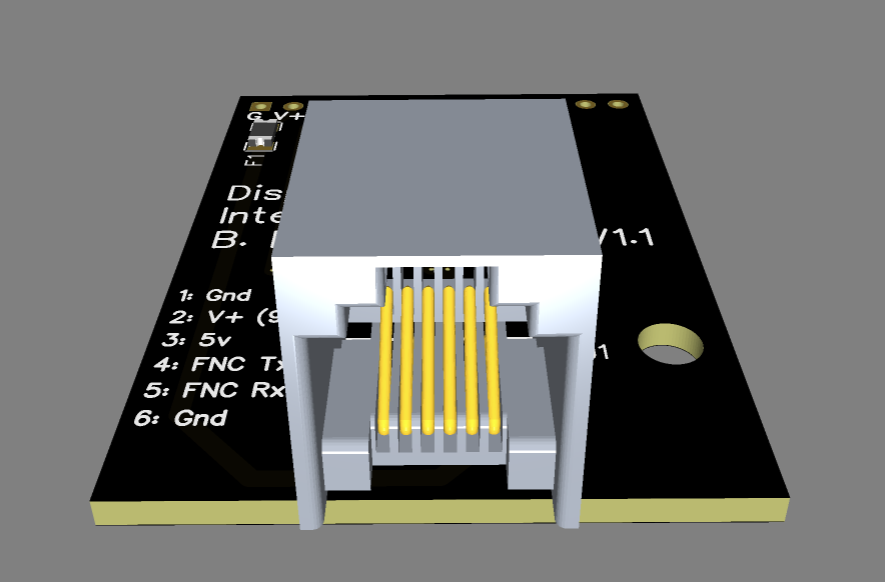
Here is an example schematic that adds a little protection to the CPU. This should be connected directly to the gpio of the ESP32.
¶ I/O Expander Design guidelines
- We only support expanders via UART control right now.
- Use an RJ12 connector for the UART
- If a second UART is available, consider a pass through pendant connector.
- Consider how firmware upgrades are done. For STM32 designs, most people will use the pass through upgrade via bootloader, but you should include the ST-Link header.
- We do not have experience with other controllers, but easy firmware upgrades need to be considered.
- Some sort of debugging LED should be used to help with support.
¶ Layout Issue Hall of Shame
- gpio.2 Pull up prevents programming of ESP32
- gpio.12 Pull up changes voltage of flash. Cannot be programmed and crashes existing firmware
¶ Developer Policy on User Created Hardware
The primary firmware developers cannot provide a high level of support for DIY and hacked hardware. We cannot donate our valuable time to your unique project. This policy is a result of many lost hours of time due to hardware problems.
Reading hand drawn schematics and trying to interpret hardware from photographs takes extra time. If we cannot reproduce the problem with our known working hardware, we may step back from active support. Feel free to continue discussing the issue on Discord and Github with other members of the community.
We are always concerned when a new issue is presented. It may indicate a problem with the firmware. We will usually try to reproduce your problem on known working hardware. If your hardware worked on a previous of the firmware, but fails on a newer version, please revert to the older version to verify it still works and nothing on your wonky and fragile hardware has changed.