¶ Testing Step Pins
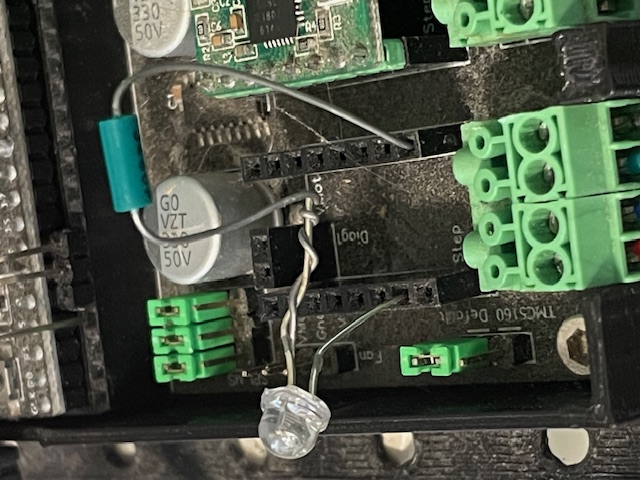
When debugging motion problems it can help to test that the motor driver STEP pin is pulsing correctly. One way to do that is by attaching an LED + resistor to the STEP pin on either the motor driver socket or, for an external driver setup, to the STEP output that goes to the external driver.

Any color LED will work. Any resistor value between about 270 ohms and 10K ohms will work. The lower the value, the brighter the LED. You can solder the resistor to the short lead of the LED, or just twist the leads together as shown here.
The long LED lead goes to the STEP connector, while the free resistor lead goes to GND.
Then you can run motion commands and watch the LED to see if the STEP pin is pulsing. The movie below shows the result of the command G0 X200
We recommend using FluidTerm or the WebInstaller terminal for testing like this, because there is less that can go wrong compared to testing with WebUI.
After the first G0 X200, a subsequent G0 X200 would not cause any motion because the X axis is already at 200. So to move again you would need to use a different coordinate. You could alternate between G0 X200 and G0 X0.
The LED gets brighter during acceration, maintains constant brightness during constant-speed motion, and gets dimmer during deceleration.
If the LED starts out in the on (lit) state, it could be because the STEP pin is configured for active low (:low on the config file pin specifier). In that case, the LED will get dimmer during acceleration, etc.
The brightness depends on several factors:
- The IO voltage (3.3V or 5V)
- The value of the resistor (small resistor => brighter LED)
- The inherent brightness/efficiency of the LED
- The step rate, which depends on max_rate_mm_per_min and steps_per_mm
- The value of pulse_us
It is usually possible to see the LED light up even if the brightness is low.
¶ Direction Pins
A similar technique can be used for direction pins; just connect the long LED lead to the direction pin instead of the step pin. With the direction pin the LED will be full-on or full-off rather than ramping up or down in brighness. You can change its state by changing the direction of motion. It will remain at the last direction's state. If you, for example, alternate between G0 X200 and G0 X0, it should turn on and off or vice versa, depending of the :low attribute on the direction pin in the config file.
¶ Using TMC Drivers
If your system has a TMC driver that requires configuration with UART or SPI, this technique will not work directly because, when you remove the driver to plug in the LED, FluidNC will not be able to configure the missing driver and will fail to start. In this case, you have two options:
- You could leave the TMC driver in its socket and solder the LED lead to the TMC driver's STEP pin. The resistor lead could also be soldered to the TMC GND pin, or otherwise connect to any convenient GND location on the board.
- Alternatively, you could temporarily change the config file to specify a standard_stepper driver type for that motor for the purpose of this test. If the TMC drivers are in a daisy-chained configuration, you might need to change all of the motors to standard_stepper, lest the missing TMC module should break the daisy chain.
¶ External Drivers
A similar technique works with external drivers. Connect the long LED lead in place of the PUL+ signal on the external driver, and the free resistor lead in place of PUL-.