¶ RS485 (Modbus) Spindles
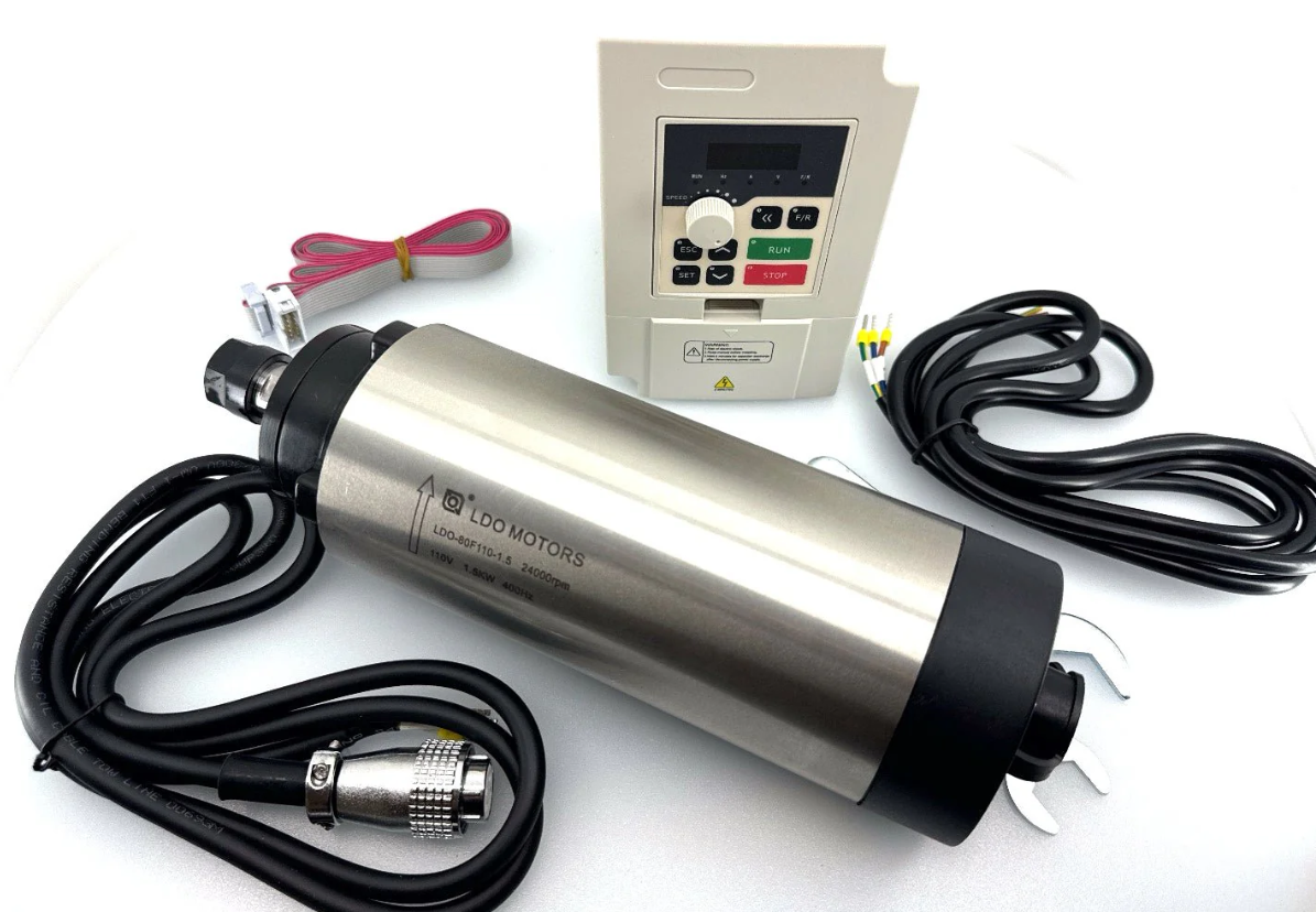
These spindles are controlled with a RS485 connection via Modbus protocol.
VFD support is very expensive and time consuming for the developers. There is no way we can afford the cost and setup space in our work areas to have all of the VFDs. We recommend the Huanyang to all new users. After thousands of hours of use and support cases, this one has proven to be the easiest to use. We also have access to this one and can give better tech support.
¶ Overview
¶ RS485 Circuitry
As far as FluidNC is concerned, the RS485 looks like a simple UART. You need to have some circuitry external to the microcontroller to convert the signals to the differecial voltage pair used by RS485. You can read more about RS485 here.
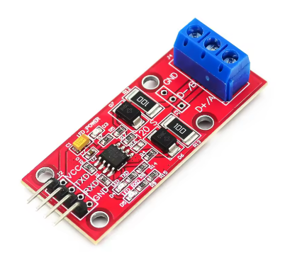
Many FluidNC controllers have built in RS485 hardware. If your controller does not directly support RS485, you can add an external TTL to RS485 adapter. Be sure to get one that is 3.3v compatible.
The RS485 is a half duplex connection with FluidNC as the master. The master side must control the direction of communication in the half duplex circuit. It can do this with an RTS pin on the UART or automatically if the RS485 circuit supports that.
¶ UART setup
Here is a typical config file setup. rts_pin: is not used if the direction control is automatic. Set the baud to what your VFD needs. 9600 is recommended. Faster will not gain you anything. Modbus uses the 8N1 mode. Make sure the pins match your hardware. Most of the controller wiki pages will give you a config example for an RS485 UART.
uart1:
  txd_pin: gpio.14
  rxd_pin: gpio.15
  rts_pin: gpio.13
  baud: 9600
  mode: 8N1
¶ RS485 Wiring
RS485 terminals can be labeled A and B or + and -. Typically (A connects to -) and (B connects to +), but many people have found that the 2 wires need to be swapped. Often there is a ground wire. RS485 is designed to isolate devices, so connecting a common ground defeats that feature. Most people have better luck without a ground connection between the controller and VFD.
You should use a 20 - 22 AWG twisted pair of wires. If the cable is shielded connect the shield wire to ground at one end only.
¶ Signal LEDs
If you have Tx and Rx LEDs at the controller side the Tx should blink a few times per second, per the poll_ms: config value. The Rx LED should blink right after. It does it so quickly that they may appear to blink at the same time.
- If the Rx LED stays on, try swapping A and B at the controller end.
- If only the Tx LED blinks, then there is likely a communication problem.
- Check the wiring
- Try swapping A and B
- Check that the baud rate and that the addressed (ids) match.
- See if you are using the correct protocol.
¶ Chosing a VFD
There are a lot of VFDs out there. We support a lot of them. Adding a new one is time consuming, expensive and hard to support. Try to choose one that is already supported. If you want the best reliability and support from us, choose the Huanyang or YL620.
¶ General VFD Info
VFD means Variable Frequency Drive. They create a variable 3 phase AC voltage. Many of the settings like maximum speeds are often in Hz rather than RPM. You typically multiple Hz * 60 to get RPM, like 400Hz * 60 = 24000 RPM, but some motors may have more poles than normal and the 60 might be a different number.
A minimum speed is typical with VFD spindles because they lack power and can overheat at lower speeds. Most VFDs have settings for minimum and maximum speeds (or frequencies)
If you have $message/level=debug you will see when the values are retrieved from the VFD. "ModbusVFD" will be replaced with whatever config section name you are using.
[MSG:DBG: ModbusVFD: got maxRPM 24000]
[MSG:DBG: ModbusVFD: got minRPM 6000]
Most VFDs also have 0-10V control. If you are struggling with RS485, try that.
¶ Spindle Configs
¶ ModbusVFD (Generic)
This is the base class for all other spindles. You should only need to use this spindle config when you are trying to use an unsupported spindle.
This shows all of the config file items when used with Huanyang as an example. If you are actually using the Huanyang, use this format.
ModbusVFD:
  uart_num: 1
  modbus_id: 1
  debug: 0
  poll_ms: 250
  retries: 5
  spinup_ms: 6000
  spindown_ms: 6000
  tool_num: 100
  speed_map: 0=0.00% 0=25.00% 6000=25.00% 24000=100.00%
  off_on_alarm: false
  atc:
  m6_macro:
  s0_with_disable: false
  disable_with_s0: false
  model: Huanyang
  min_RPM: 6000
  max_RPM: 24000
  cw_cmd: 03 01 01 > echo
  ccw_cmd: 03 01 11 > echo
  off_cmd: 03 01 08 > echo
  set_rpm_cmd: 05 02 rpm*100/60 > echo
  get_min_rpm_cmd: 01 03 0b 00 00 > 01 03 0B minRPM*60/100
  get_max_rpm_cmd: 01 03 05 00 00 > 01 03 05 maxRPM*60/100
  get_rpm_cmd: 04 03 01 00 00 > 04 03 01 rpm*60/100
- uart_num:
- Type: Integer (0-2) Default: 1
- Details: This links it to the uart you configured.
- modbus_id:
- Type: Integer (0-247) Default: 1
- Details: This has to match your VFD's value. When is doubt, use 1.
- debug:
- Type: Integer (0-5) Default: 2
- Details: Used to activate various level of debug messages.
- 0 No debug info
- 1 No debug info
- 2 Will show when there is no response, and speed info
- 3 Will show the Rx and Tx messages
- poll_ms:
- Type: Integer (250-20000 milliseconds) Default: 250
- Details: time between messages
- retries:
- Type: Integer Default: 5
- Details: Retries before it alarms
- spinup_ms:
- Type: Integer (0-60000 milliseconds) Default: 0
- Details: How long it waits for the spinup. This should be equal to or greater than your VFD's value or you will get an alarm.
- spindown_ms:
- Type: Integer (0-60000 milliseconds) Default: 0
- Details: How long it waits for the spinup. This should be equal to or greater than your VFD's value or you will get an alarm.
- speed_map:
- Type: Speed map
- Details: You do not need to set this value. If left blank it will create a speed_map from the min and max values retrieved from the VFD.
- model:
- Type: String (default empty)
- Details: This is used for support purposed only. It will help us when you are having problems.
- speed_map
- Type: speed_map string
- Details: See this wiki section
- min_RPM:
- Type: Integer
- Details: See this wiki section
- off_on_alarm:
- atc:
- Details: See this wiki entry
- m6_macro: See this wiki entry
- **s0_with_disable:
- Details: See this wiki entry
- disable_with_s0:
- Details: See this wiki entry
- max_RPM:
- Type: Integer
- Details: See this wiki section
- cw_cmd:
- Type: String (Modbus Command)
- Default: Empty
- Details: A Modbus command template telling the VFD to run in the clockwise (forward) direction.
- ccw_cmd:
- Type: String (Modbus Command)
- Default: Empty
- Details: A Modbus command template telling the VFD to run in the counter clockwise (reverse) direction.
- off_cmd:
- Type: String (Modbus Command)
- Default: Empty
- Details: A Modbus command template telling the VFD to stop the spindle.
- set_rpm_cmd:
- Type: String (Modbus Command)
- Default: Empty
- Details: A Modbus command template telling the VFD to run at a given speed.
- get_min_rpm_cmd:
- Type: String (Modbus Command)
- Default: Empty
- Details: A Modbus command template for retrieving the minimum speed from the VFD.
- get_max_rpm_cmd:
- Type: String (Modbus Command)
- Default: Empty
- Details: A Modbus command template for retrieving the maximum speed from the VFD.
- **get_rpm_cmd:++
- Type: String (Modbus Command)
- Default: Empty
- Details: A Modbus command template for retrieving the VFDs current running speed.
¶ Modbus Command Templates
You only need to read this if you are using a spindle that is not supported. See the preconfigured spindles.
In general, a standard Modbus command consists of a one-byte "modbus ID" followed by a few command and data bytes, followed by two CRC check bytes. The modbus ID and CRC are handled by common code so the command template does not specify them.
The Modbus standard defines a few common command formats, but different VFDs are very loose in their interpretations of how to use them, so the Command Template format lets you specify the exact bytes to send and receive. Here is an example of a simple command that does not contain any variable data:
cw_cmd: 06 20 00 00 12 > echo
The ModbusVFD driver would send the modbus_id byte, then the hex bytes 0x06, 0x20, 0x00, 0x00, 0x12, followed by the CRC. It would then expect to receive a VFD response that is the same as the command, hence "echo'. In general, the received sequence is not necessarily the same as the command, so you will often need to specify something other than "echo".
Commands can send or receive RPM speed values. In this example, we send the speed scaled to device units of deciHz (the VFD represents 400 Hz as 4000).
set_rpm_cmd: 06 20 01 rpm*10/60 > echo
The driver would send the modbus_id byte, followed by the hex bytes 0x06, 0x20 and 0x01. It would convert the requested speed in RPM to the device units by multiplying by 10 (deciHx per Hz) and dividing by 60 (seconds per minute) and send the resulting (two-byte) number, followed by the CRC check bytes. In scaling specifiers, multiplication, if present, must precede division. Both are optional. In this example, *10/60 is equivalent to /6, so you could write just rpm/6 . "> echo" again means that this VFD responds to such commands by repeating them back.
This example receives a speed value:
get_rpm_cmd: 03 20 0b 00 01 > 03 02 rpm*60/10
The driver would send the fixed command modbus_id, 0x03, 0x20, 0x0b, 0x00, 0x01, CRC, then expect to receive the response modbus_id, 0x03, 0x02, (2-byte data), CRC. The two data bytes are combined into a 16-bit integer and scaled back from device units to RPM by multiplying by 60 and dividing by 10 - the inverse of the scaling from RPM to device units.
In addition to "rpm", you can specify "minrpm" in the get_min_rpm command and "maxrpm" in the get_max_rpm_command. For some VFDs, it is possible to get both the min and max speeds with a single command. This example works for one VFD:
get_max_rpm_cmd: 03 03 08 00 02 > 03 04 minrpm*6 maxrpm*6
If you can get both min and max in one command, it is not necessary to specify get_min_rpm_cmd; just use get_max_rpm_cmd for both. For most VFDs this will not be possible so you will need both commands.
The generic ModbusVFD driver can in fact be used to run most of the already-supported ones. Here is a complete example for YL620:
ModbusVFD:
  uart_num: 1
  modbus_id: 1
  model: YL620
  cw_cmd: 06 20 00 00 12 > echo
  ccw_cmd: 06 20 00 00 22 > echo
  off_cmd: 06 20 00 00 01 > echo
  set_rpm_cmd: 06 20 01 rpm*10/60 > echo
  get_max_rpm_cmd: 03 03 09 00 01 > 03 02 maxrpm*60/10
  get_min_rpm_cmd: 03 03 08 00 01 > 03 02 minrpm*60/10
  get_rpm_cmd: 03 20 0b 00 01 > 03 02 rpm*60/10
Other common Spindle config items like tool_num, spinup_ms, spindown_ms, m6_macro, atc, disable_with_s0 and s0_with disable can also be specified. If get_rpm_cmd is present, spinup_ms and spindown_ms are ignored, since the driver will use get_rpm_cmd to determine when the VFD has reached the target speed.
¶ Scaling Specifiers
The named data items "rpm", "minrpm" or "maxrpm" can be scaled to VFD device units with a "scaling specifier" of the form:
[%][*N][/N]
where [...] indicates that the field is optional and N is a decimal integer. If the data item appears in the outgoing command - before the '>' - the scaling is applied to the value in RPM to convert to device units, and the converted value is inserted into the outgoing packet. The only item name that can be used for outgoing data is "rpm", in **set_rpm_command". If the data item appears in the response - after the '>' - the device unit value is retrieved from the response packet and then scaled to RPM. All of the item names are available for responses.
*N causes multiplication by the decimal number N. /N causes division by the decimal number N. For the few VFDs that represent speed values as a percentage of the maximum speed, % multiplies by 100 and divides by maxRPM, thus calculating the percentage, which can then be multiplied and/or divided by a constant. % only works correctly in set_rpm_command, for outgoing commands.
¶ Details of Scaling Operations
- For get.. commands, the 16-bit value is extracted from the VFD response packet. The divisor is set to 1. If the scaling specification starts with '%', the value is multiplied by 100. Then, if the next item in the scaling specifier is '*N', the value is multiplied by N. Then, if the next item in the scaling specifier is '/N', the value is divided by N. Finally, the value is stored in the named variable (minrpm, maxrpm, or rpm). (The '%' notation is rarely used for get operations.)
- For set_rpm_command, the divisor is set to 1. If the scaling specification starts with '%', the input value is multiplied by 100 and the divisor is set to maxRPM. Then, if the next item in the scaling specifier is '*N', the value is multiplied by N. Then, if the next item in the scaling specifier is '/N', the divisor is multiplied by N. Finally, the value is divided by the divisor and then stored in the VFD command packet. (Deferring the actual division until the end prevents loss of integer precision.)
¶ Pre Configured VFDs
These are based on the ModbusVFD class described above. All of the modbus commands will default to the proper values, so do not add them to your config.
¶ Huanyang

This is the standard Huanyang VFD (all power levels). Part numbers start with Hy, like HY02D223B-T.
The VFD registers need to be set up prior to use. FluidNC will not change any of the registers. Read your VDF documentation on how to do that. Here are some typical values that work for most spindles.
| Register | Value | Description |
|---|---|---|
| PD001 | 2 | RS485 Control of run command |
| PD002 | 2 | RS485 Control of frequency |
| PD004 | 400.00 | Base frequency as rated on spindle |
| PD005 | 400.00 | Maximum frequency Hz (400Hz * 60sec/min = 24000rpm) |
| PD011 | 100.00 | Minimum speed in Hz (Typ. Air cooled 120, Water cooled 100) |
| PD014 | 6.0 | Acceleration time in seconds |
| PD015 | 6.0 | Deceleration time |
| PD023 | 1 | Enable reverse |
| PD141 | 220.0 | Spindle Voltage |
| PD142 | 3.7 | Max current (typ. 0.8kw=3.7) |
| PD143 | 2 | Poles |
| PD144 | 3000 | Revolutions at 50Hz |
| PD163 | 1 | RS485 Modbus address |
| PD164 | 1 | Baud rate of 9600 |
| PD165 | 3 | RS485 Mode RTU, 8N1 |
Check your RS485 adapter documentation for proper wiring methods and connections. Here is some information on the RS485 module.
uart1:
  txd_pin: gpio.14
  rxd_pin: gpio.15
  rts_pin: gpio.13
  baud: 9600
  mode: 8N1

Huanyang:
  uart_num: 1
  modbus_id: 1
  tool_num: 0
¶ YL620
YL620 is a Chinese VFD made by Yalang.

The VFD registers need to be set up prior to use. FluidNC will not change any of the registers. Read your VFD documentation on how to do that. Here are some typical values that work for most spindles.
The Hz values given below indicate the frequency that is sent to the motor. A typical
2-pole motor will rotate once per Hz, so to get RPMs you multiply Hz (cycles/sec) times
60 (sec/min). So a 2-pole motor at 400 Hz runs at 400 * 60 = 24,000 RPM nominally. In
practice it will run slightly slower due a real-world factor called "slip". A 24,000 RPM nominal motor might actually run at 23,500 with no load and 23,000 RPM under load.
| Register | Value | Description |
|---|---|---|
| P00.00 | 4000 | Main frequency in deci-HZ - 4000 is 400.0 Hz |
| P00.01 | 3 | Command Source. 3 is for control via RS485 |
| P03.00 | 3 | RS485 Baud Rate. 3 is for 9600 |
| P03.01 | 1 | Modbus Address. Typically you want to use 1. |
| P03.02 | 2 | RS485 Data format. 2 is 8 data bits, 1 stop bit, no parity |
| P03.08 | 1000 | Lowest frequency in deci-Hz - 1000 is 100.0Hz |
uart1:
  txd_pin: gpio.14
  rxd_pin: gpio.15
  rts_pin: gpio.13
  baud: 9600
  mode: 8N1

YL620:
  uart_num: 1
  modbus_id: 1
  tool_num: 0
  speed_map: 0=0% 0=25% 6000=25% 24000=100%
  off_on_alarm: false
¶ H100

Additional Information Includes a PDF of a manual that appears to be correct.
Possibly Incorrect Manual This is a manual for "LSLV-H100+". It does not seem to match the behavior of the H100 VFDs that most users have.
This is the standard H100 VFD (all power levels). Part numbers typically look like H100-xxx.
The VFD registers need to be set up prior to use. FluidNC will not change any of the registers. Read your VDF documentation on how to do that.
The most relevant sections are:
F011 (min frequency)
F005 (max frequency)
uart1:
  txd_pin: gpio.26
  rxd_pin: gpio.16
  rts_pin: gpio.4
  baud: 9600
  mode: 8N1

H100:
  uart_num: 1
  modbus_id: 1
  tool_num: 0
  speed_map: 0=0% 0=25% 6000=25% 24000=100%
¶ P2 Series

The Huanyang P2 series inverters, also dubbed 'H2A/H2B/H2C' or sometimes 'P2A' inverters are supported as well. This product was designed to be the 2nd generation of the popular Huanyang inverter from hy-electrical.com. These VFD's are small, and low power VFD's are usually white or gray. The sticker on the side of the inverter clearly tells that this is the inverter in question.
The manual can unfortunately be a bit confusing at times when it comes to setting up the RS485 connection.
At the top of the box is a RS485 connector with a 4-wire screw terminal. Wiring should use these 4 pin:
- GND
- A = RS+485
- B = RS-485
- VCC
ALWAYS read the manual for VFD's! This is imperative to get motor speed etc. all correct. The H2x series inverters use real RPM values, so you need to set these accordingly, or the device won't work correctly. Next to that, you need to set certain settings to get RS485 working correctly, most notably:
| Setting | Value | Description |
|---|---|---|
| F0.02 | 7 | Set RS485 mode |
| F0.04 | 2 | Set RS485 mode |
| F0.09 | 4 | Set RS485 mode |
| F9.00 | 4 | 19200 baud |
| F9.01 | 0 | 8,N,1 parity |
| F9.02 | 1 | ModBus address |
| F9.05 | 0 | Non-standard modbus mode |
| F9.07 | 0 | Write operations responded |
¶ NowForever
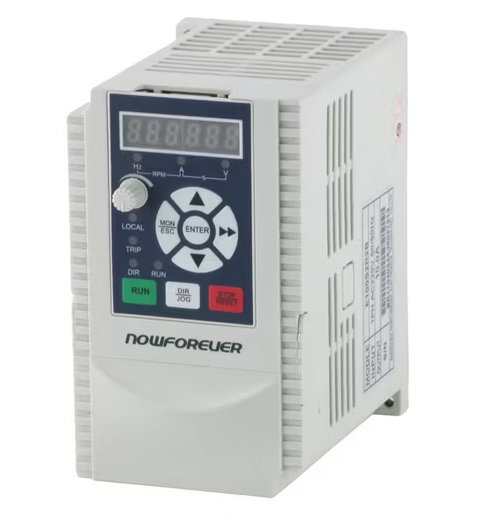
Manufacturer: Shenzhen NowForever Electronics Technology CO.,LTD.
Website: http://www.nowforever.cn/
The D series of VFDs can be found in the control box of Chinese CNC6040 cnc routers.
Unfortunately there is no manual for the D series so all of this information is based on the manual for the E series.
However there is a comparison chart made by someone else that shows that almost all parameters are the same.
The manual for the E series can be found online in various places by searching for NowForever e100 manual using your preferred search engine.
Comparison chart (german, also contains link for e series manual): http://moh-computer.de/frequenzumformer-parameter/
The current implementation for supporting NowForever VFDs has been tested against the D100S1R5B (D series, 1PH AC 220V 50/60hz input, 8A output) inverter.
It should work for other VFDs in the D series too as well as the E series since its manual has been used for reference of the parameters and protocol details.
This includes controlling the direction through another input of the VFD. (See manual for details)
Here is a selection of the parameters needed to make the VFD (D and E series) communicate with FluidNC:
Selection of RS485 as control and frequency source:
| Register | Value | Description | Possible Values |
|---|---|---|---|
| P0-000 | 2 | Command source | 0: Keypad 1: Control inputs 2: RS485 |
| P0-001 | 0 | Frequency source | 0: main frequency source 1: auxiliary frequency source 2: main + aux 3: max(main, aux) 4: selected by control input |
| P0-002 | 6 | Main frequency source selection | 0: Keypad Potentiometer 1: Keypad Up Down Arrow 2: AIN1 3: AIN2 4: Multistep speed 5: PID 6: RS485 7: Internal PLC |
RS485 parameters:
| Register | Value | Description | Possible Values |
|---|---|---|---|
| P0-055 | any free address between 1 and 31 | Address of VFD | 1- 31: slave addresses 2: master address |
| P0-056 | 2 works just fine | Baudrate | 0: 2400bps 1: 4800bps 2: 9600bps 3: 19200bps 4: 38400bps |
| P0-057 | 0 | Data framing | 0:1 start bit, 8 data bits, no parity, 1 stop bit 1: 1 start bit, 8 data bits, even parity, 1 stop bit 2: 1 start bit, 8 data bits, odd parity, 1 stop bit |
Setting min and max speed:
| Register | Value | Description | Possible Values |
|---|---|---|---|
| P0-007 | Whatever your spindle can handle | Max frequency | Min frequency - 600hz |
| P0-008 | Whatever your spindle can handle | Min frequency | 0 - Max frequency |
The following registers are read / written to by FluidNC:
Read access only:
| Register | Description |
|---|---|
| 0x007 | Max frequency in hz * 100, same as config parameter P0-007 |
| 0x008 | Min frequency in hz * 100, same as config parameter P0-008 |
| 0x300 | Current fault number 0 = no fault 1-18 = fault number |
| 0x500 | VFD status Bit 0: run, 1=run, 0=stop Bit 1: direction, 1=ccw, 0=cw Bit 2: control, 1=local, 0=remote Bit 3: sight fault, 1=fault, 0=no fault Bit 4: fault, 1=fault, 0=no fault Bit 5-15: reserved |
| 0x502 | Current output frequency in hz * 100 |
Write access only:
| Register | Description |
|---|---|
| 0x900 | VFD control Bit 0: run, 1=run, 0=stop Bit 1: direction, 1=ccw, 0=cw Bit 2: jog, 1=jog, 0=stop Bit 3: reset, 1=reset, 0=dont reset Bit 4-15: reserved |
| 0x901 | Speed to be set in hz * 100 |
Example YAML config:
uart1:
  txd_pin: gpio.14
  rxd_pin: gpio.15
  rts_pin: gpio.13
  baud: 9600
  mode: 8N1

NowForever:
  uart_num: 1
  modbus_id: 1
  tool_num: 0
  speed_map: 0=0% 24000=100%
  off_on_alarm: false
¶ Danfoss VLT 2800
Contributed via this PR
¶ Siemens V20
Contributed via this PR
uart1:
  txd_pin: gpio.17
  rxd_pin: gpio.16
  rts_pin: gpio.4
  baud: 9600
  mode: 8E1

SiemensV20:
  uart_num: 1
  modbus_id: 1
  tool_num: 0
  speed_map: 0=0% 24000=100%
This following are supported like the ones above, but we do not have specifi setup info yet.
¶ Mollom G70
¶ Danfoss VLT2800
¶ Delta MS300 Series Drive (contributed via Discord)
uart1:
  txd_pin: gpio.15
  rxd_pin: gpio.16
  rts_pin: gpio.14
  baud: 9600
  mode: 8N1

ModbusVFD:
  uart_num: 1
  modbus_id: 1
  min_rpm: 2000
  max_rpm: 24000
  spinup_ms: 3000
  spindown_ms: 5000
¶ Folinn BD600
board: 6x CNC Controller
name: PortalCnc by MP (@snoozemoose on Discord)


## Begin Folinn_BD600_24kRPM_@800Hz
##
# Manual where all commands are specified: https://cononmotor.com.au/wp-content/uploads/2017/09/BD600-Manual.pdf
# Initial note: This spindle defines CCW as forward running.
#
### GENERIC FORMULA FOR ANY AC MOTOR ###
# RPM = 60 x 2 x Hz / NumPoles
# Hz = RPM x NumPoles / 120
#
# This GPenny spindle has 4 poles, max Hz is 800, max rpm is 24k.
# 4 poles gives Hz = RPM * 4 /120 = RPM / 30
#
### Device speed _SET_ operation ###
# The value to send is the percentage of max Hz * 100 which is calculated as:
#   targetHz / maxHz * 100 * 100
# Note; The RPM percentage of max RPM is exactly the same as the Hz percentage of max Hz.
# Note2; 100 percent is here defined as 100, not 1.0
#
# Example; setting a speed of 3k RPM (same as 100 Hz in this case)
# calculates to (3 / 24 * 100) * 100 = 1250.
# Using Hz we get the same result: (100 / 800 * 100) * 100 = 1250
#
# The set_rpm_cmd command therefore shall send the value RPM / maxRPM * 100 * 100 which is defined as:
#    rpm%*100 using the syntax of FluidNC Generic ModbusVFD
#
### Device speed _GET_ operation ###
# The value received from the VFD for all fetch operations are defined as:
#    currentHz * 10
# Given that this VFD and Spindle has the formula RPM = Hz * 30 (see above),
# the RPM is calculated from the received value as follows:
#    receivedValue = currentHz * 10
#    currentHz = receivedValue / 10
# And since RPM = Hz * 30
#    RPM = receivedValue / 10 * 30
#    RPM = receivedValue * 3
# Therefore, the get rpm commands defines the value calculation as:
#    rpm*3 using the syntax of FluidNC Generic ModbusVFD

uart1:
  txd_pin: gpio.15
  rxd_pin: gpio.16
  rts_pin: gpio.14
  cts_pin: NO_PIN
  baud: 9600
  mode: 8N1

ModbusVFD:
  spinup_ms: 500
  spindown_ms: 1000
  uart_num: 1
  modbus_id: 1
¶ Defining the speed range
Most VFD spindles have a working RPM range. There is usually a minimum recommended speed. At slow speeds VFD spindles don't have much power and spindles cooled by a fan on the shaft won't have enough speed to cool the spindle. They also have a maximum speed that is determined by the spindle or the VFD manufacturer.
Most VFDs have settings or registers for these speeds. You should definately set it in the VFD if possible. There are 3 ways to that FluidNC can be configured to deal with the speed range.
-
(Recommended) Leave the
minRPM,maxRPMandspeed_mapconfig items blank in your spindle config. FluidNC will read the min and max from the VFD and create the appropriate minRPM, maxRPM and speed_map values on the fly for the config. -
You can put
minRPM,maxRPMconfig items in your config file. FluidNC will still read the values, but use the config file values to create a speed_map. -
You can put a speed_map in your config file. This will be used instead of the minRPM and maxRPM in the config file or read from the VFD. Some people may use this method if the actual measured speed is different than the VFD is trying to create. Read all about speed_maps here.
For reference: If the values are read from the VFD and you have set $message/level=debug, the values will print at startup.
Grbl 4.0 [FluidNC v4.0.2-pre4 (AllInOnModbusVFD-f3679a83-dirty) (esp32s3-wifi) '$' for help]
[MSG:DBG: Huanyang: got maxRPM 24000]
[MSG:DBG: Huanyang: got minRPM 6000]
Due to timing issues, the values may appear at different places in the startup messages.
¶ The best way to get started.
-
Get your VFD and spindle running in manual control mode. It makes no sense to try RS485 until you know the VFD is working correctly. Test everything, like min RPM, max RPM, spin up and down times, forward and reverse.
-
Wire your RS485 adapter to the VFD. Devices are typically labeled with the symbols A and B or + and -. Wire the same symbols together. If you have A/B at one end and +/- at the other, A goes to - and B goes to +. Wire ground to ground.
-
If things don't work, try swapping the A/B or +/- wires at one end. If that does not work, try removing the ground connection wire with both combinations of the A/B, +/- wiring.
-
Double check that you are in RS485 control mode. Check that the baud rate setups match on each end.
¶ Troubleshooting
-
VFD RS485 Unresponsive Message This is normal if your VFD is not connected, not powered on, or connected correctly. RS485 can be complicated for non-engineers. We cannot help you fix this for free (seriously donate big before you ask). Please read the internet on how RS485 works and how to wire it. If you want a simpler interface, try 0-10V control.
-
MSG:INFO: RS485 No response When the terminal is constantly repeating
[MSG:INFO: RS485 No response], it can be difficult to interact with FluidNC. Send$Message/Level=Noneto temporarily suspend all messages. You can type this in FluidTerm or the Web Installer terminal even while the messages keep popping up. Return it to the INFO level by sending$Message/Level=Infoafter you fix the problem.