¶ Probe

¶ Overview
Probes are used to find the surface of the workpiece. Most commonly this on the Z axis, but FluidNC supports doing it with any axis. The probe circuit is an input to FluidNC, similar to a limit switch. The most common method uses the electrical conductivity of the bit and a metal plate or puck of known thickness on the material to complete a circuit. You could also use any kind of circuit that opens or closes on contact.
FluidNC will move the probe towards the surface. When contact is detected FluidNC will output the location on the serial port and other connected channels. It will then decelerate to a stop to prevent any loss of steps that might occur due to an immediate stop. If you supply the P parameter, FluidNC will zero the axis using the offset provided.
Multipoint surface leveling is not supported by the firmware. A simple Gcode version would have too many parameters to make this practical. A much better solution is to have a GUI prompt you for all the grid parameters. Many gcode senders support this. They then alter the streaming gcode to fit the material profile. FluidNC supports this method.
¶ Probe pins
We currently support two probe input pins. probe_pin: and toolsetter_pin:. All gcode logic treats them as the same thing. There is no way to target one or the other with G38. The primary reason we created two pins is to allow N.C. and N.O (or PNP and NPN) probes to be used together without an external OR'ing circuit. If you have both and send a G38 command activating either probe will do the same thing. They show up as separate switches in the status command to help you debug wiring and config issues.
¶ Config File
- pin:
- Type: Pin (input)
- Range: gpio
- Default: NO_PIN
- Details: This is the signal from the probe.
- toolsetter_pin:
- Type: Pin (input)
- Range: gpio
- Default: NO_PIN
- Details: This is an optional second probe.
- check_mode_start:
- Type: Boolean
- Default: true
- Details: This will force a probe check before a probe is started.
- hard_stop:
- Type: Boolean
- Default: false
- Details: If true the axis will do a hard stop rather than decelerate. This can be used with fragile bits that might break with the overtravel needed for deceleration. It is likely to be less accurate at higher speeds where the motor might skip a few steps without deceleration.
- probe_hard_limit: (new in v3.9.9)
- Type: Boolean
- Default: false
- Details: If true the probes will act like hard limits, trigger an alarm and immediately stop motion when triggered during non probing motion. This is to prevent accidental damage to probes.
Config Example:
probe:
  pin: gpio.34
  toolsetter_pin: NO_PIN
  check_mode_start: true
  hard_stop: false
  probe_hard_limit: false
¶ Setup
Make sure the pin has the right attribute for active high or low. You can verify this by sending the '?' status command. You should not see the "P" in the status response in the Pn: section. If you see the P invert the active state.
Next, manually activate the probe by triggering the switch, completing the circuit or whatever is needed to activate it. While in the active state you should see the P in the Pn: section when you send the ? command.
Until you pass a manual test, you should not attempt a real probe action.
¶ Using the probe
Basic probing uses a G38.2 command to probe to a switch or electrical contact. You can adjust the active state of the signal with the high/low attribute.
If you set check_mode_start: true it will verify the probe is not touched before the move. If it is you will get an alarm 4
If the probe move completes without activating a probe, input it will fail with an alarm 5.
If the probe is successful, it will issue a message like this [PRB:151.000,149.000,-137.505:1] with the machine position at the time of the touch specified. The 1 at the end specifies a successful probe. After touching, the machine will decelerate to a stop. This means the machine location will differ from the location in the message after the probe. It is usually only a tiny amount, but you should account for it. The over travel is proportional to the speed. It could break your bit if the over travel is high or the bit is very fragile.
If the probe fails, it will issue a message like this [PRB:0.000,0.000,0.000:0]. The 0 at the end indicates a failed probe.
You need to specify move axis parameters and a feedrate.
- G38.2 Z-5 F200 This would probe towards the work position Z-5 with a feed rate of 200.
- G38.2 G91 Z-5 F200 The G91 parameter will cause it to move down in Z by 5 with a feed rate of 200. Note: Be aware that G91 will persist and affect subsequent g codes. You should reset it to G90 if that was the previous mode.
- G53 G38.2 Z-125 F200 P16 This will probe toward Z-125 in machine space (G53)
You can probe towards any point in any or multiple axes at once. Soft limits will be respected. If the command requests a maximum travel that exceeds the range and soft limits are true for the axis, you will get an alarm.
¶ Setting Work Zero
The value in the PRB message is the exact point where the probe activates. The machine will then decelerate to a stop. The machine will no longer be at the probe point even if the probe is going slowly. The best way to set a work zero is to use the G10 L2 Px command with x being the coordinate system. P0 would be the current system. P1 through P6 would be used to specify G54-G59. To set the current work Z to 0 after getting [PRB:151.000,149.000,-137.505:1] send G10 L2 P0 Z-137.505, using the z value from the PRB message. If you have a plate or other offset, just add that to the PRB value.
¶ Optional P parameter
You can use an optional "P" parameter that specifies the thickness (or offset from 0) of the probe device, like a plate or puck.
Upon successful probe the offset of the current system is zeroed with the P value applied. This will make it much easier for displays and senders to deal with probing.
Example: G38.2 G91 F80 Z-20 P8.00
This will probe an incremental (G91) amount of -20 in Z. It will set the probe location to 8.00 on the Z axis in the current work coordinate system.
Notes:
- After the probe touch, the status will show the axis location to be a little off from the probe location. This is due to the deceleration after the probe touch. The probe location is accurate to the actual touch point. If you want to minimize the over travel, use a lower speed (best) or faster acceleration (in your config file).
- You can only specify movement in one axis when you use the P parameter.
¶ Troubleshooting
¶ Testing the probe
You can test the probe by sending $message/level=debug. Afterwards, every switch change will issue a message, for example:
[MSG:DBG: Probe 0]
[MSG:DBG: Probe 1]
[MSG:DBG: Limit switch tripped for X motor 0]
[MSG:DBG:  X Pos Limit 0]
[MSG:DBG:  X Pos Limit 1]
[MSG:DBG: Limit switch tripped for X motor 0]
The interesting messages for probe testing are Probe 0 (meaning probe inactive/not touched) and Probe 1 (probe active/touched). If you see no such messages when you manually touch and release the probe, perhaps there is a config file problem in the probe: .. pin: section per the config example above. If the messages are backwards - 0 when touched and 1 when released, you need to either add or remove the :low modifier from the pin assignment.
After things are working, you can send $message/level=info to stop the debug messages.
¶ ALARM:4 Probe fail.
Probe is not in the expected initial state before starting the probe cycle when trying to probe. You cannot start a probe cycle if the probe is already active. See the setup section above.
¶ Macros
Macros can be used to probe and set the current work coordinates.
¶ Example using standard gcode
This assumes that you are probing in Z using a touch plate that is on top of the work and is 10 mm thick. It also assumes that you are above the probe location of the plate.
G21 ; use millimeters
G91 ; move in relative motion mode
G38 Z-30 F80 P10; probe a maximum of 30mm down at a rate of 80
G90 ; use absolute motion mode
G0 Z50 ; retract to 30 above work
¶ Using gcode expressions
; dual speed probe macro

; set parameters
#<fast_rate>=160
#<slow_rate>=80
#<probe_dist>=100
#<probe_offset>=10
#<retract_height>=5

G38.2 G91 Z[-#<probe_dist>] F#<fast_rate> ; probe fast
G0 Z3  ; retract a little
G38.2 G91 Z[-#<probe_dist>] F#<slow_rate>; probe slowly
#<mpos_z_touch>=#5063 ; save the z touch WCO location
G0 Z[#<retract_height>+#<probe_offset>] ; retract
G10 L2 P0 Z[#<mpos_z_touch>+#<probe_offset>]
G91 G0 Z[#<retract_height>+#<probe_offset>]
¶ A macro to find the Z distance between the work Z0 and a tool sensor Z0
This macro probes for the work Z0 using an electronic probe like this. It sets the work Z0 at the tip of the probe. It then uses the probe to find the top of a tool length sensor like this. It then calculates the distance between the 2 Z heights and stores it in the G59 Z value. Other macros can then use this value to change tools and compensate for the tool length changes.
; This program sets the work Z 0 at the tip of the probe
; It also finds the tool sensor activation point.
; It calculates the Z difference between the work 0 and the toolsetter
; The difference is stored in the G59 Z so future M6 macros can use it.
;
; !!! Before running this move the probe over the work !!!
;

#<ets_x_mpos_mm>=1.5              ; x location of the ets
#<ets_y_mpos_mm>=139.0            ; the Y location of the ets
#<ets_z_mpos_min_mm>=-40          ; the G38 target in Z
#<probe_seek_rate_mm_per_min>=200
#<probe_feed_rate_mm_per_min>=80
#<work_probe_min_mm>=-35          ; probe max G53 travel in Z
#<retract_height>=3.0             ; retract between seek and feed probes
#<safe_z_mpos_mm>=-1.0            ; top of Z for safe XY moves

#<was_metric>=#<_metric>

G21 ; all moves are in mm.
G49 ; reset the TLO

;set the work 0 at the probe tip.
G38.2 G53 Z#<work_probe_min_mm> F#<probe_seek_rate_mm_per_min>
G53 G1 Z[#<_abs_z>+#<retract_height>] F200
G38.2 G53 Z#<work_probe_min_mm> F#<probe_feed_rate_mm_per_min> P0 ; probe slower and set the work 0
#<z_mpos_mm>=#5063 ;save the work mpos

G53 G0 Z#<safe_z_mpos_mm>

; find the ets Z in mpos
G53 G0 X#<ets_x_mpos_mm> Y#<ets_y_mpos_mm>
G38.2 G53 Z#<ets_z_mpos_min_mm> F#<probe_seek_rate_mm_per_min>
G53 G1 Z[#<_abs_z>+#<retract_height>] F200
G38.2 G53 Z#<ets_z_mpos_min_mm> F#<probe_feed_rate_mm_per_min>

; determine the offset
#<ets_offset_mm>=[#5063 - #<z_mpos_mm>]
G10 L2 P6 Z#<ets_offset_mm> ; store the offset in G59

G53 G0 Z#<safe_z_mpos_mm>

; restore G20
o100 if [#<was_metric> EQ 0]
  G20
o100 endif


(print,ETS offset from work Z is #<ets_offset_mm> mm)
This can be used as an m6 macro after the above macro has been run. It uses a tool length sensor to compare the length of the tool to the probe and create a TLO (tool length offset) value to compensate for the new tool length.
; This is intended to be used as an M6 macro
;
;

#<chg_x_mpos_mm>=75.0                ; use change pos x
#<chg_y_mpos_mm>=139.0                ; use change pos y
#<ets_x_mpos_mm>=1.5              ; x location of the ets
#<ets_y_mpos_mm>=139.0            ; the Y location of the ets
#<ets_z_mpos_min_mm>=-40          ; the G38 target in Z
#<probe_seek_rate_mm_per_min>=200
#<probe_feed_rate_mm_per_min>=80
#<retract_height>=3.0             ; retract between seek and feed probes
#<safe_z_mpos_mm>=-1.0            ; top of Z for safe XY moves

G53 G0 Z#<safe_z_mpos_mm>
G53 G0 X#<chg_x_mpos_mm> Y#<chg_y_mpos_mm>
G4 P0.25 ; wait for motion to complete.
(print,Please install tool number: #5400, then resume job)
M0 ; pause

; go over ets
G53 G0 X#<ets_x_mpos_mm> Y#<ets_y_mpos_mm>

; find the ets Z in mpos
G38.2 G53 Z#<ets_z_mpos_min_mm> F#<probe_seek_rate_mm_per_min>
G53 G1 Z[#<_abs_z>+#<retract_height>] F200
G38.2 G53 Z#<ets_z_mpos_min_mm> F#<probe_feed_rate_mm_per_min>
G53 G0 Z#<safe_z_mpos_mm>
G43.1 Z[#5063 + #5323]
(print,ETS is #5063  G59 Z is offset #5323  mm)
¶ Examples
¶ 3 Axis Electronic Probe
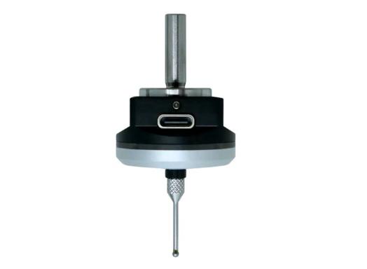
This probe has a USB-C connector. It is not a USB device. It comes with a special cable breaking it out to wires. I (Bart) have seen 3 wire and 4 wire versions. Mine is a 3-wire version.
- Red is +5V to +24V.
- Black is Gnd.
- Yellow is the signal. The signal is low when activated and high (red wire voltage) when inactive.
The XY sensing can be used to find the edges of workpieces or the center of holes.
The Z can be used to find the top of work but generally needs to be used with a tool length sensor, because you need accurate tool length offsets in order to use it with actual cutting bits.
¶ Cheap tool length sensor
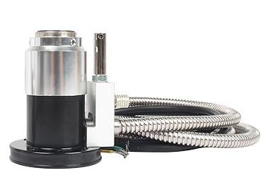
This one has 2 N.C. mechanical switches. One is the more accurate tool sensor that activates first. The other is an over travel switch that activates about 5mm lower than the first. You wire the length sensor to the probe_pin or toolsetter_pin. You can wire the over travel switch to a control pin input such as reset_pin or estop_pin.
Since these are mechanical switches, it is easy to use a meter to find which wires below to each switch.
I (Bart) find that this works well with the 3 axis electronic probe above. It has a lower activation force.
¶ Another Cheap Tool setter
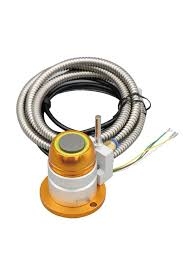
This is a widely available tool setter. It is cheap but works pretty well. There are various colors and finishes. They have 2 activation points.
- Tool setter signal. This is the first activation point and is probably the most accurate. It should be hooked up to your probe input.
- Overtravel signal. This activates after (lower) than the other signal. It is designed as a warning that you are about to crash. This will save your bit and maybe other things if your Z axis is very strong. You can hook this to any alarm input, like reset or e-stop. You can also hook it up as a Z limit switch if you use hard limits. If you are short on inputs, put it in parallel or serial with an existing limit switch.
The wire colors are random, but the switches are simple mechanical switches so you can easily figure out the wiring with a meter. They sell both N.C. and N.O. switch versions. Use a multimeter to find out which pairs go together and whether they are N.C. or N.O. N.C. would report as closed when not touched.
If you have four wires (orange, brown, green and blue), typically orange and brown are for the probe activation, and the green and blue are for the overtravel switch.
This should be mounted to a very flat surface. Tools with different widths could touch at different heights if the ETS surface is at an angle.
¶ Using the toolsetter
If you want it to "automatically" compensate for tool height, you will need to write some gcode expression macros or use the manual ATC feature.