¶ Trinamic Drivers
Trinamic drivers have many features that can be set by FluidNC. These drivers are typically completely powered by the motor voltage. VCC pins are only used for I/O voltage reference. Therefore, the motor voltage must be on at all times to use these. The ESP32 on the controller can often be powered by the USB connection, but the motors cannot. If the motor voltage is not present at turn and the ESP32 is powered by the USB, the drivers will not respond. If the drivers are failing the startup tests, try clicking the ESP32 reset button when the main power is on.
There is a command that allows you to run the motor driver initialization at any time. It is $Motors/Init or $MI. If you forget to turn on the main power, you can turn on the power and then send the $MI command. A message will be sent regarding the success or failure of that. You can send that command whenever you want to check the motor status (not in run mode)
Examples
[MSG:ERR: X Axis driver test failed. Check connection]
[MSG:ERR: Y Axis driver test failed. Check motor power]
[MSG:ERR: Z Axis driver test passed]
We are not experts on these drivers. We use a third-party open source library (TMCStepper) to control them. We do not know the best register settings for them. Many of them will be specific to your machine and motors. You will have to experiment. They are generally great drivers, but temperamental. Please don't expect the FluidNC developers to solve your issues with these motors.
Note: You can buy some Trinamic drivers on modules in "stand alone" or "stepstick" mode. These cannot be setup by FluidNC and you should configure them as stepstick drivers.
Driver Not Detected: The drivers are detected using the UART or SPI connection. If you get this message, it is most likely a communication problem. Check the configuration and wiring.
¶ SPI Controlled (TMC2130 and TMC5160)
SPI controlled drivers use SPI (Serial Peripheral Interface) to directly control the features and modes of the driver. SPI has 2 modes, independent and daisy chain mode. This depends on how the SPI is wired on the controller.
 daisy chain
For independent mode each driver needs its own cs_pin:. They do not use a spi_index:, so each spi_index: should be set to -1.
In daisy chain mode they all use the same cs_pin:, but each requires its own spi_index:. The spi_index: is a number from 1 to how many drivers you have. The spi_index: indicates the position of the driver on the SPI daisy chain. You must set the index based on the PCB design and axis letter order.
In a daisy chain arrangement, MOSI loops through all the motors, and then returns to the controller as MISO. To write to the second driver, you write to the first with the data for the second driver, then write dummy data to the first to push the first data to the second. Reading data has the same issue when you must push the data through the drivers at the end of the chain. There FluidNC needs to know about all drivers, even ones you are not using. You must define something for all drivers.
¶ TMC2130
Links
Shares step_pin, direction_pin, and disable_pin with Standard Stepper, plus:
¶ cs_pin
- Type: Pin (output)
- Range: gpio or i2so
- Default:
NO_PIN
Chip select pin. For independent mode each chip needs its own. For daisy chain mode, you should only define it on the motor with spi_index: 1
¶ spi_index
- Type: Integer
- Range: -1 to 127
- Default:
-1
For independent mode all must be -1 (default). For daisy chain mode they must be unique (see above). Start with index 1 and increment by 1 for the next motor. They need to be defined in the order the chips are daisy chained together. Every physical position in the chain must be represented by a motor entry, even unused ones, or the chain's data alignment breaks.
¶ r_sense_ohms
- Type: Float
- Range: 0.0 to 1.00
- Default:
0.0(not a real functional value -- see below)
This is the value of the current sense resistor used with the driver. This is needed to set the current. The compiled default of 0.0 is a placeholder, not a usable value -- there's no generic default that's correct across driver modules, so you must always set this explicitly to match your actual hardware. Genuine TMC2130 modules are usually 0.11 Ohm.
¶ run_amps
- Type: Float
- Range: 0.05 to 10.0
- Default:
0.5
This value sets the driver's output current when the driver is outputting steps.
¶ hold_amps
- Type: Float
- Range: 0.05 to 10.0
- Default:
0.5
This value sets the driver's output current when the driver is not outputting steps.
¶ microsteps
- Type: Integer
- Range: 1 to 256 (should be 1,2,4,8,16,32,64,128 or 256 )
- Default:
16
This sets the microstepping level.
¶ stallguard
- Type: Integer
- Range: -64 to 63
- Default:
0
Stallguard threshold level. A higher value makes stallGuard2 less sensitive and requires more torque to indicate a stall. Only meaningful when run_mode or homing_mode is StallGuard. See datasheet for more details.
¶ stallguard_debug
- Type: Boolean
- Default:
false
This turns on debugging information that can help you tune stallguard. It should not be left on during normal use.
¶ toff_disable
- Type: Integer
- Range: 0 to 15
- Default:
0
TOFF off time and driver enable. A value of 0 disables the driver. See the TMC2130 datasheet regarding this.
¶ toff_stealthchop
- Type: Integer
- Range: 2 to 15
- Default:
5
TOFF in stealthchop mode. See the TMC2130 datasheet regarding this.
¶ toff_coolstep
- Type: Integer
- Range: 2 to 15
- Default:
3
TOFF in Coolstep mode. See the TMC2130 datasheet regarding this.
¶ run_mode
- Type: Enumeration
- Range: StealthChop, CoolStep or StallGuard
- Default:
StealthChop
Chopper algorithm while running: StealthChop (very quiet), CoolStep (runs cooler, allows higher current), or StallGuard (CoolStep plus stall/load detection).
¶ homing_mode
- Type: Enumeration
- Range: StealthChop, CoolStep or StallGuard
- Default:
StealthChop
Chopper algorithm while homing (same choices as run_mode) -- StallGuard is typically used here for sensorless homing.
¶ use_enable
- Type: Boolean
- Default:
false
Uses disable_pin as an active enable signal (inverted sense) instead of the ordinary active-disable sense -- some driver modules wire this pin the opposite way from the FluidNC default.
¶ diag0_error
- Type: Boolean
- Default:
false
Enables the DIAG0 pin to signal driver error conditions. SPI-driver-specific -- not available on the UART-controlled Trinamic drivers.
¶ diag0_otpw
- Type: Boolean
- Default:
false
Enables the DIAG0 pin to signal an over-temperature pre-warning. SPI-driver-specific -- not available on the UART-controlled Trinamic drivers.
¶ diag0_int_pushpull
- Type: Boolean
- Default:
false
Configures the DIAG0 pin's output stage as push-pull instead of open-drain. SPI-driver-specific -- not available on the UART-controlled Trinamic drivers.
- False: DIAG0 is open collector output (active low)
- True: DIAG0 is push pull output (active high)

¶ Config Example
  tmc_2130:
    cs_pin: gpio.17
    spi_index: -1
    r_sense_ohms: 0.110
    run_amps: 0.750
    hold_amps: 0.250
    microsteps: 32
    stallguard: 0
    stallguard_debug: false
    toff_disable: 0
    toff_stealthchop: 5
    toff_coolstep: 3
    run_mode: StealthChop
    homing_mode: StealthChop
    use_enable: false
    step_pin: gpio.12
    direction_pin: gpio.26
    disable_pin: NO_PIN
Daisy chain example:
  x:
    steps_per_mm: 800.000
    max_rate_mm_min: 5000.000
    acceleration_mm_per_sec2: 100.000
    max_travel_mm: 300.000
    soft_limits: false
      tmc_2130:
        cs_pin: gpio.17
        spi_index: 1
        r_sense_ohms: 0.110
        run_amps: 0.750
        hold_amps: 0.750
        microsteps: 16
        stallguard: 0
        stallguard_debug: false
        toff_disable: 0
        toff_stealthchop: 5
        toff_coolstep: 3
        run_mode: CoolStep
        homing_mode: CoolStep
        use_enable: true
        step_pin: gpio.12
        direction_pin: gpio.14
        disable_pin: NO_PIN

  y:
    steps_per_mm: 800.000
    max_rate_mm_min: 5000.000
    acceleration_mm_per_sec2: 100.000
    max_travel_mm: 300.000
    soft_limits: false
    homing:
      cycle: 2
      positive_direction: false
      mpos_mm: 150.000
      feed_mm_per_min: 100.000
      seek_mm_per_min: 200.000
      settle_ms: 500
      seek_scaler: 1.100
      feed_scaler: 1.100

    motor0:
      limit_neg_pin: NO_PIN
      limit_pos_pin: NO_PIN
      limit_all_pin: gpio.39
      hard_limits: true
      pulloff_mm: 1.000
      tmc_2130:
        spi_index: 2
        r_sense_ohms: 0.110
        run_amps: 0.750
        hold_amps: 0.750
        microsteps: 16
        stallguard: 0
        stallguard_debug: false
        toff_disable: 0
        toff_stealthchop: 5
        toff_coolstep: 3
        run_mode: CoolStep
        homing_mode: CoolStep
        use_enable: true
        step_pin: gpio.27
        direction_pin: gpio.26
        disable_pin: NO_PIN
¶ TMC2208:
TMC2208 drivers can operate in standalone STEP/DIR mode . Values such as microstep, run current and hold current, amongst others, can also be configured via UART.
A step_pin and a direction_pin must always be defined in the motor config. Enabling the motor can be done either using a disable_pin: or enabled via UART with use_enable: true in the config file.
The TMC2208 drivers are not addressable. This means that when daisy chaining these drivers, config values will be passed to all drivers, and it is not possible to configure parameters for individual drivers. It is important to note that the values that will be applied will be those defined in the last motor / axis listed in the config file. Values that are not defined in this final motor / axis config will fall back to default, overriding any values set in previous motor/ axis configurations.
Shares step_pin, direction_pin, disable_pin, r_sense_ohms, run_amps, hold_amps, microsteps, toff_disable, toff_stealthchop, use_enable, run_mode, homing_mode, stallguard, stallguard_debug, and toff_coolstep with TMC2130, plus:
¶ addr
- Type: Integer
- Default:
0
Hardware UART address of the chip. TMC2208/TMC2225 have a fixed address of 0, so this field has no effect on them (it matters for TMC2209/TMC2226, which set their real address via MS1/MS2 pins).
¶ cs_pin
- Type: Pin
- Default:
NO_PIN
Rarely used -- present because this driver's config shares a base class with the SPI driver family, but a UART-mode chip doesn't need a chip-select pin. Only relevant for a cs_pin-based UART switching setup.
¶ uart_num
- Type: Integer
- Default:
-1(must be set -- there is no usable default)
Which top-level uartN: section this chip's UART register interface runs over. Required -- the config fails to load if this isn't set.
Daisy chain example:
  axes:
  shared_stepper_disable_pin: gpio.1

  x:
    steps_per_mm: 400
    max_rate_mm_per_min: 1500
    acceleration_mm_per_sec2: 100
    homing:
      cycle: 2
      allow_single_axis: true
      positive_direction: false
      mpos_mm: 0
      feed_mm_per_min: 50
      seek_mm_per_min: 400
    motor0:
      limit_all_pin: gpio.2:low
      hard_limits: true
      pulloff_mm: 1
      tmc_2208:
        step_pin: gpio.3
        direction_pin: gpio.4:low
        # THESE VALUES ARE OVERIDEN BY Y AS TMC2208 IS NOT ADDRESSABLE.
        # ALL VALUES ARE TAKEN FROM LAST DEFINED MOTOR/AXIS
        # run_amps: 1.5
        # hold_amps: 0.5
        # microsteps: 8
        # disable_pin: 10

  y:
    steps_per_mm: 400
    max_rate_mm_per_min: 1500
    acceleration_mm_per_sec2: 100
    homing:
      cycle: 2
      allow_single_axis: true
      positive_direction: true
      mpos_mm: 290
      feed_mm_per_min: 50
      seek_mm_per_min: 400
    motor0:
      limit_all_pin: gpio.5:low
      hard_limits: true
      pulloff_mm: 1
      tmc_2208:
        step_pin: gpio.6
        direction_pin: gpio.7
        # THESE ARE THE LAST DEFINED VALUES
        # AND WILL BE THE VALUES APPLIED TO
        # ALL DRIVERS IN THE DAISY CHAIN
        microsteps: 16
        r_sense_ohms: 0.110
        # IF NOT DEFINED - DEFAULT VALUES WILL BE USED
        # run_amps: 0.5
        # hold_amps: 0.5
        disable_pin: NO_PIN
        uart:
          txd_pin: gpio.8
          rxd_pin: gpio.9
          baud: 115200
          mode: 8N1
¶ TMC5160
Shares step_pin, direction_pin, disable_pin, r_sense_ohms (typically 0.075 Ohm for TMC5160), run_amps, hold_amps, microsteps, toff_disable, toff_stealthchop, use_enable, cs_pin, spi_index, run_mode, homing_mode, stallguard, stallguard_debug, toff_coolstep, diag0_error, diag0_otpw, and diag0_int_pushpull with TMC2130, plus:
¶ tpfd
- Type: Integer
- Range: 0 to 15
- Default:
4
TMC5160-specific passive fast decay time register value -- affects current ripple/step smoothness at low microstepping in StealthChop mode. Consult the TMC5160 datasheet before changing from the default.
¶ Config Example
tmc_5160:
      step_pin: gpio.12
      direction_pin: gpio.14
      disable_pin: NO_PIN
      cs_pin: gpio.17
      r_sense_ohms: 0.050
      run_amps: 1.800
      hold_amps: 1.250
      microsteps: 8
      toff_disable: 0
      toff_stealthchop: 5
      use_enable: false
      run_mode: CoolStep
      homing_mode: CoolStep
      stallguard: 16
      stallguard_debug: false
      toff_coolstep: 3
      tpfd: 4
A lot of people have had trouble with these drivers. They are very advanced, and the settings have to be finely tuned to your machine. They also can draw a lot of power. Make sure you have a power supply with a lot of extra capacity. We cannot provide too much support because we are not experts on the chip. Please respect our support time. For extra fine tuning see the "pro" versions lower on this page.
Potentiometers Many TMC5160 modules have potentiometers on them. The TMCStepper library we use sets TMC5160 chips in an *i_scale_analog" mode. This means the pot is used to scale that current value that is set digitally. You should turn these pots up to full or where they output 2.5V. This will allow you to use the full current range of the drivers.
Here is a chart for the current. Most modules use a 0.075Ohm resistor, so for those the maximum current is 3.1A

¶ UART Controlled
¶ TMC2209
This section is for UART controlled chips. Each chip must have a hardware based addressing system. We do not support write only communication (1 way), because it is critical that we know the chips are responding to commands.
It is very difficult to use TMC2209 plug in modules or controllers that do not directly support Trinamic UART controlled chips. You must externally wire the UART and you must figure out how to wire the UART externally.
TMC2209 drivers need a step_pin and a direction_pin. They can either use an disable_pin: or enable via UART with a use_enable: true in the config file.
You must define pins for the uart in a uart section of the config file. Each motor must have a uart_num:. This could allow multiple uarts to be used to get past the 4 address per uart limit.
Shares step_pin, direction_pin, disable_pin, r_sense_ohms, run_amps, hold_amps, microsteps, toff_disable, toff_stealthchop, use_enable, run_mode, homing_mode, stallguard_debug, toff_coolstep, addr, cs_pin, and uart_num with TMC2208, plus:
¶ stallguard
- Type: Integer
- Range: 0 to 255 (0 = least sensitive, 255 = most sensitive)
- Default:
0
StallGuard sensitivity threshold. Only meaningful when run_mode or homing_mode is StallGuard. Note this range is different from every SPI-driven Trinamic type (tmc_2130/tmc_5160/etc.), which use -64 to 63 instead.
¶ homing_amps
- Type: Float
- Range: 0.0 to 10.0
- Default:
0.0(substituted with run_amps if left at 0)
Motor current while homing. Leaving this at its default 0 isn't literally "zero current" -- FluidNC detects the default and substitutes run_amps instead, so omitting this field entirely is equivalent to setting it equal to run_amps. This fallback is specific to TMC2209; no other Trinamic driver type has a homing_amps field at all.
¶ shared_address_write_only
- Type: Boolean
- Default:
false
Acknowledges that this chip's UART address (uart_num + addr) is intentionally shared with other TMC2209 motors on the same bus rather than uniquely assigned -- required on every driver sharing that address, or the config fails to load with a "must set shared_address_write_only: true" error. Since replies can't be distinguished on a shared address, this also requires cs_pin: NO_PIN and disallows stallguard_debug, and every driver sharing the address must agree on the same current/microstep/mode settings (a mismatch is a config-load error, not a silent inconsistency).
¶ Config Example
    motor0:
      limit_neg_pin: gpio.36:low
      tmc_2209:
        uart_num: 1
        addr: 0
        cs_pin: NO_PIN
        r_sense_ohms: 0.110
        run_amps: 1.000
        hold_amps: 0.500
        microsteps: 16
        stallguard: 0
        stallguard_debug: false
        toff_disable: 0
        toff_stealthchop: 5
        toff_coolstep: 3
        run_mode: StealthChop
        homing_mode: StealthChop
        homing_amps: 0.50
        use_enable: false
        direction_pin: gpio.12
        step_pin: gpio.14
        disable_pin: NO_PIN
¶ TMC UART
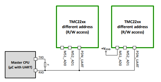
The UART is typically connected like this, with a single connection to all drivers. The drivers need the address (addr: in config) set from 0 to 3 via the MSn_ADn pins via hardware connections.
¶ TMC UART with cs_pin
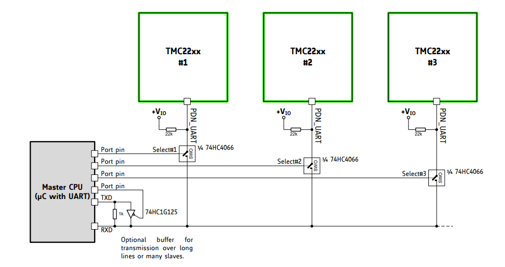
The cs_pin can be used to control a chip to switch the UART. This can allow you to get around the limit of 4 addresses for the chips. The address can be dynamic. You can also connect the cs_pin to an address pin.
¶ Design Notes
The VCC on the stepstick modules is used as the I/O reference. It should be 3.3V when directly connected to ESP32s. The driver VCC is generated internally from VMOT, so these chips will not communicate unless the VMOT is connected.

¶ tmc_5160Pro & tmc_2160Pro Motors (Expert Mode)
The tmc_5160Pro and tmc_2160Pro motors are for advanced users who want direct control over the most important and commonly used registers of the driver. We can add more registers if they are needed.
Currently the driver uses the same register values for both normal and homing modes.
You will need the datasheet to understand these registers
Shares step_pin, direction_pin, and disable_pin with Standard Stepper, plus:
¶ cs_pin
- Type: Pin
- Default:
NO_PIN
SPI chip-select for this driver. In independent (non-daisy-chained) SPI mode each driver needs its own; in a daisy chain, define this only on the motor with spi_index: 1.
¶ spi_index
- Type: Integer
- Range: -1 to 127
- Default:
-1
-1 means independent SPI mode. In a daisy chain, each driver gets a distinct position number (1, 2, 3, ...) in chain order.
¶ use_enable
- Type: Boolean
- Default:
false
Uses disable_pin as an active enable signal (inverted sense) instead of the ordinary active-disable sense.
¶ CHOPCONF
- Type: Integer (raw register value)
- Default:
322994520
Raw TMC5160 CHOPCONF register value. Consult the TMC5160 datasheet -- these 7 register fields are not semantic settings (there is no run_amps/microsteps/etc. here at all), just the literal register contents applied at init.
¶ COOLCONF
- Type: Integer (raw register value)
- Default:
0
Raw TMC5160 COOLCONF register value.
¶ THIGH
- Type: Integer (raw register value)
- Default:
0
Raw TMC5160 THIGH register value.
¶ TCOOLTHRS
- Type: Integer (raw register value)
- Default:
0
Raw TMC5160 TCOOLTHRS register value.
¶ GCONF
- Type: Integer (raw register value)
- Default:
4
Raw TMC5160 GCONF register value.
¶ PWMCONF
- Type: Integer (raw register value)
- Default:
3289120798
Raw TMC5160 PWMCONF register value.
¶ IHOLD_IRUN
- Type: Integer (raw register value)
- Default:
7948
Raw TMC5160 IHOLD_IRUN register value (packs both hold and run current directly, unlike the semantic run_amps/hold_amps fields used by tmc_5160).
There is also a semantic (non-Pro) tmc_2160 type, identical to tmc_5160 (run_amps/microsteps/etc. rather than raw registers) -- separate from tmc_2160Pro described here.
¶ Register Calculators
Most registers are a number built up from many smaller values. There is a Google Sheet that can help you create the register values from these values. Make your own copy of the sheet to get edit rights. You will still need to use the datasheet to determine what values to use.
TMC5160 and TMC2160 work exactly the same. The only difference is the name in the config file.
¶ Config Examples
      tmc_5160Pro:
        step_pin: I2SO.2
        direction_pin: I2SO.1
        disable_pin: I2SO.0
        cs_pin: I2SO.3
        spi_index: -1
        use_enable: false
        CHOPCONF: 373326168
        COOLCONF: 0
        THIGH: 0
        TCOOLTHRS: 0
        GCONF: 4
        PWMCONF: 3289120798
        IHOLD_IRUN: 3852
      tmc_2160Pro:
        step_pin: I2SO.2
        direction_pin: I2SO.1
        disable_pin: I2SO.0
        cs_pin: I2SO.3
        spi_index: -1
        use_enable: false
        CHOPCONF: 373326168
        COOLCONF: 0
        THIGH: 0
        TCOOLTHRS: 0
        GCONF: 4
        PWMCONF: 3289120798
        IHOLD_IRUN: 3852
If you have a working config from the normal tmc_5160 config item, you can use that as a starting point. If you set $message/level=debug, it will show you the current values of the registers.
If you are struggling to use this type of config, this might not be for you. The registers are very complex and not for newbies. Even the developers of FluidNC do not fully understand how to use them. Please don't expect support on register values. Ask TMC directly.
¶ Tips
- Currents are set in IHOLD_IRUN
- Microstepping CHOPCONF