¶ FluidNC Axes Setup
FluidNC supports 12 motors on 6 axes. This page details the different ways steps are generated, settings and integration with different hardware.
¶ Stepping:
This is an important section for the motors.
¶ engine
- Type: Enumeration
- Range: RMT | TIMED | I2S_STATIC | I2S_STREAM (some boards also support Simulator or PIO)
- Default: board-dependent (there is no single hardcoded default -- each board picks the engine matching its hardware)
This determines the method used to generate the steps in firmware. Controller board hardware is designed for either RMT or I2S stepping so you must choose a method that your controller board hardware uses. It is not possible to mix and match stepping types on different motors. The supported types are:
- RMT results in simpler hardware for projects that are not limited by GPIO pin count. It is typically used on controller boards with no more than 4 independent motor ports. It uses the RMT feature of the ESP32 chip to handle step pulse generation without wasting time in delay loops. It does so by planning a sequence of voltage transitions in advance and then triggered for each step pulse. The step and direction pins are native GPIO pins. So, if there are lots of motors, few GPIOs will be left for other uses.
- TIMED has the same pin limitations as RMT but is less efficient so there is no reason to use it. It uses the CPU to drive steppers directly which requires delays that waste CPU cycles.
- I2SO (I2S Output Only) Is a way to drive motors with fewer GPIO pins by using the ESP32's I2S bus interface hardware. It requires specific external hardware on the controller board (read more). If using I2SO hardware, there must be a valid I2SO definition in your config file. The 6-pack controller was the original board to utilize this engine. Others have since used the core design for different boards such as MKS DLC32 and TinyBee. I2S_STATIC and I2S_STREAM are identical. The two distinct names exist for historical reasons, when there were two variants with different trade-offs for speed vs latency. Now, choosing either will invoke the same code, giving high-speed, low-latency, jitter-free stepping.
- Simulator and PIO are additional engines available only on boards built with simulator or RP2040-PIO support compiled in; most controller boards won't offer them.
People often ask if the I2S method could be used for input expansion. While it is theoretically possible, there are complications that make it less attractive than other input expansion methods. We do not plan to implement I2S input. For input expansion, we recommend and support using an auxiliary MCU that communicates with the FluidNC ESP32 over a UART connection.
¶ idle_ms
- Type: Integer
- Range: 0 to 10000000
- Default:
255
A value of 255 will keep the motors enabled at all times (preferred for most projects). Any other value, either between 0-254 or from 256-10000000, will disable all the motors that many milliseconds after the last step on any motor. Note: Motors can be manually disabled at any time with the $MD command.
The use of the value 255 to mean "always enabled" is for Grbl compatibility. Grbl used an 8-bit number for this parameter so only values of 0-255 were possible. FluidNC uses a 32-bit number to permit larger values.
¶ pulse_us
- Type: Integer
- Range: 0 to 30
- Default:
4
The duration of the step pulses (microseconds). This is the "on" duration of the pulse. It typically needs an equal "off" duration. This means the max number of steps per second will be 1,000,000/(pulse_us*2). Stepper drivers will have a minimum required time length for pulses to register them. If the manufacturer provides a datasheet for the stepper driver, this value can be found there.
¶ dir_delay_us
- Type: Integer
- Range: 0 to 10
- Default:
0
The delay (microseconds) needed between a direction change and a step pulse. Many drivers do not need a delay here.
¶ disable_delay_us
- Type: Integer
- Range: 0 to 1000000
- Default:
0
Some motors need a delay from when they are enabled to when they can take the first step. This value is the number of microseconds delayed.
¶ segments
- Type: Integer
- Range: 6 to 20
- Default:
12
This sets the number of segment buffers. You should leave this at the default unless you are trying to fine tune a special application.
¶ Config Example
stepping:
  engine: I2S_STATIC
  idle_ms: 250
  pulse_us: 4
  dir_delay_us: 4
  disable_delay_us: 0
  segments: 6
¶ Speed Limitations
Step signals are sent as pulses. Each pulse has a duration as described above. The pulse_us is the "on" duration of the pulse. It typically needs an equal "off" duration. Other parameters like dir_delay_us also can contribute to the total duration of each pulse. The absolute maximum number of pulses you can send per second (Hz) is 1/(total pulse time). This has nothing to do with the speed of the processor; it is just math. Realistically the fastest you can go is in the 100kHz-125kHz range. This will be slower if you are using long pulse durations.
The config items that set this rate are steps_per_mm and maximum pulse rate. Here is the equation to find this rate.
(steps_per_mm * (max_rate_mm_per_min) / 60)
Therefore, you can see that steps_per_mm has a big impact. Do not use a larger number than you need, or max speed will suffer. Consider lowering your microstepping to get a lower steps_per_mm.
Some of this math is checked with this formula when the config file is loaded. You may get errors if rates are exceeded, you may also get crashes.
1000000 / ((2 * pulse_us) + dir_delay_us)
The speed of the processor can also come into play if a lot of processor time is required per step. High density laser engraving is one example.
if you exceed the max rate, you will get an error like this: "[MSG:ERR: Initialization error at /axes/y: Stepping rate 157750 steps/sec exceeds the maximum rate 125000]"
¶ Axes
¶ shared_stepper_disable_pin
- Type: Pin
- Range: gpio or I2SO
- Default:
NO_PIN
This is a pin that is wired to multiple motor drivers (typically all). This toggles with the motor enable/disable feature. You can also assign pins at the individual motor level.
¶ shared_stepper_reset_pin
- Type: Pin
- Range: gpio or I2SO
- Default:
NO_PIN
This is a pin that is wired to multiple motor drivers. This is a feature commonly found on stepstick driver sockets. Currently this only sets the voltage at turn on and it stays that way. You can also assign pins at the individual motor level.
¶ homing_runs
- Type: Integer
- Range: 1 to 5
- Default:
2
This sets the number of approach/pulloff touches performed per axis during a homing sequence. The default is 2 to match the Grbl style.
¶ Config Example
axes:
  shared_stepper_disable_pin: NO_PIN
  shared_stepper_reset_pin: NO_PIN
  homing_runs: 2
¶ Axis letter
axes:
  [x:|y:|z:|a:|b:|c:]
¶ Axis letters & Linear vs. rotary axes.
The axes must be used in order. If using an XZ machine, a Y axis must still be declared. If the Y axis is not defined, FluidNC will define a virtual one without any outputs. This requirement is due to a reporting issue. The reporting sends values like 000.000, 000.000, 000.000. The axes are not labeled, so you assume they are in XYZABC order. The minimum axis count is 3. If you only define X and Y a virtual Z will be created.
ABC axis will not report position in inches:
XYZ are traditionally linear axes and ABC are considered rotary axes. ABC axis can be used as linear axes with a catch; they do not report units in inches. FluidNC uses millimeters internally and scales to inches for reporting XYZ axis. However, it will not scale ABC because it assumes they are a universal scale like degrees or radians that do not change for inches.
¶ steps_per_mm
- Type: Float
- Range: 0.001 to 100000.000
- Default:
80.000
This is a float value for the resolution of the axis. These are steps from the perspective of the controller. If using a microstepping driver, multiply the motor steps by that value. The name 'steps_per_mm' is not entirely accurate. It is really 'steps_per_gcode_unit'. If a GCode command asks for a motion of one unit in G21 mode - as when going from 98 to 99 for example - FluidNC will issue 'steps_per_mm' step pulses. In G20 (inches) mode for a linear (XYZ) axis, the number of steps is multiplied by 25.4 (mm/inch). Rotary axis motion does not depend on G20 vs G21 mode; a distance of one unit for a rotary axis always issues 'steps_per_mm' pulses.
¶ max_rate_mm_per_min
- Type: Float
- Range: 0.001 to 250000.000
- Default:
1000.000
Maximum feed rate (rapids and feed moves alike are capped here) for this axis.
¶ acceleration_mm_per_sec2
- Type: Float
- Range: 0.001 to 100000.000
- Default:
25.000
Acceleration used for this axis's motion ramps.
¶ max_travel_mm
- Type: Float
- Range: 0.1000 to 10000000.0
- Default:
1000.000
Working length of the axis. Measured from axis location after pulling off limit switch. If using a limit switch at the other end of travel for a hard limit, make sure max_travel_mm will not reach the second switch. If the second switch is pressed before the soft limit takes effect, an alarm will be triggered.
¶ soft_limits
- Type: Boolean
- Default:
false
If set to true, commands that would cause the machine to exceed max_travel_mm will be aborted. Jog commands will be constrained in this mode, so it is not possible to get a soft limit alarm while jogging. The jog will simply stop before the end of travel. Soft limits rely on an accurate machine position. This typically requires homing first. If you use soft limits alway home the axis before moving the axis via jogs or gcode.
¶ idle_disable
- Type: Boolean
- Default:
true
You can use this to ignore the idle disable (idle_ms:). If you want an axis to always stay on, you can set this to false. This could be used on Z axes to prevent them from falling or on an RC servo axis to keep it enabled.
Example:
axes:
  x:
    steps_per_mm: 800.000
    max_rate_mm_per_min: 4500.000
    acceleration_mm_per_sec2: 100.000
    max_travel_mm: 180.000
    soft_limits: true
¶ Homing
Homing is an optional feature that can move to a specified machine location that is determined by switches or sensors at the end of one or more axes. The end of the homing process establishes the origin of the "machine coordinate system". Homing is optional because most CNC workflows depend only on the "work coordinate system" whose origin is relative to the stock, not the overall machine. Homing typically involves multiple "cycles", in which one or more axes are moved to their ends. For example, it is common to home the Z axis in the first cycle, moving it all the way to the top, so that the tool does not hit stock or clamping fixtures during a subsequent cycle where X and Y are moved to their ends.
These keys are for the homing at the axis letter level. Even if an axis has more than one motor, it still homes towards one end and at a specific speed.
¶ cycle
- Type: Integer
- Range: -1 to MAX_N_AXIS (board-dependent, typically 6)
- Default:
0 - Interactions: multi-axis homing cannot be used with CoreXY, because 2 motors are used for each axis move.
Homing cycles determine each axis home. Cycles allow you to home axes one at a time or group a few axes into a single cycle for multi-axis homing. Assign the same number to multiple axes to home them in the same cycle. Many people would home the Z first (cycle: 1) and then might home X and Y at the same time (cycle: 2)
- A setting of 1 or greater enables the axis for homing with
$H. Anything lower than 1 will be an inactive cycle and no physical homing will occur for that axis. - A setting of 0 (the default) means it will not home with
$H, but you can still home it with$H<axis>(as long as allow_single_axis stays true) - A value of -1 means the machine will not move, but the current machine position (mpos) position of the axis will be set to the mpos_mm value for the axis. This can be used for axes that don't have any switches.
Typically, you would put the Z axis on cycle: 1 and the other axes on higher cycles.
¶ allow_single_axis
- Type: Boolean
- Default:
true
Allows single axis homing for the axis (example: $HX to home the X axis).
Set to false if you do not have limit switches, or to block the command. You might want to block it because a single axis home unlocks the machine even though other axes may not be homed. Soft limits are only accurate on homed axes and will not protect a machine that has not homed all axes.
¶ positive_direction
- Type: Boolean
- Default:
true
Controls the direction in which the axis moves when homing. true will home in the positive direction, where positive means moving towards a higher position value.
¶ mpos_mm
- Type: Float
- Default:
0.000
Sets the machine position after homing and limit switch pull-off in millimeters. If you want the machine position to be zero at the limit switch, set this to zero. Keep in mind the homing direction you choose this number. No range is enforced by this item -- it accepts any float.
¶ seek_mm_per_min
- Type: Float
- Range: 1.000 to 100000.000
- Default:
200.000
Speed at which axis moves to touch the limit switch for the first time to get a rough position. The axis will pull-off the limit switch and move at the speed indicated by feed_mm_per_min to touch the limit switch for a second time for a more precise home position.
¶ feed_mm_per_min
- Type: Float
- Range: 1.000 to 100000.000
- Default:
50.000
Movement speed for second contact with limit switch to get precise home position. Usually, a slow speed because the axis will be close to the limit switch and a slower speed will often yield a more precise/consistent home position.
¶ settle_ms
- Type: Integer
- Range: 0 to 1000
- Default:
250
Amount of time (in milliseconds) the machine will pause between each homing cycle to allow the machine to settle from the previous homing cycle.
¶ seek_scaler
- Type: Float
- Range: 1.0 to 100.0
- Default:
1.1
seek_scaler * max_travel equals distance homing axis will move before the operation fails if it has not reached the limit switch. This multiplier allows the axis to move farther than max_travel to account for extra distance the axis pulls-off the limit switch (mpos_mm).
¶ feed_scaler
- Type: Float
- Range: 1.0 to 100.0
- Default:
1.1
Multiplied by the pulloff_mm to calculate max distance the axis will travel back to the switch after the first pull-off before it fails. If using switches with a lot of variability or sensorless homing a larger value might be required to guarantee the switch triggers the second time.
Some closed loop motors like servos home themselves and will ignore many of settings like the pulloff and speeds
¶ Config Example
axes:
  x:
    homing:
      cycle: 2
      allow_single_axis: true
      positive_direction: false
      mpos_mm: 1.000
      seek_mm_per_min: 200
      feed_mm_per_min: 50
      seek_scaler: 1.5
      feed_scaler: 1.5
¶ Motor Settings
You can have up to two motors per axis letter. They are defined as motor0: and motor1:. If you want to learn about or implement auto squaring of the axis, see this page.
¶ limit_neg_pin
- Type: Pin
- Range: gpio
- Default:
NO_PIN
Pin used to detect limit switch activation on the negative side of axis travel.
¶ limit_pos_pin
- Type: Pin
- Range: gpio
- Default:
NO_PIN
Pin used to detect limit switch activation on the positive side of axis travel. This switch will often be just beyond the max_travel limit.
¶ limit_all_pin
- Type: Pin
- Range: gpio
- Default:
NO_PIN
Used when you want switches at both ends of travel wired to the same pin. If limit_all_pin is specified, do not specify a limit_neg_pin or a limit_pos_pin. A drawback to using this feature is that FluidNC does not know which end of travel is causing the trigger. It cannot determine which way to move to clear the switch. Because of this, switches must be cleared manually before homing.
¶ hard_limits
- Type: Boolean
- Default:
false
Set this to true when you want to use the switches defined above as hard limits. Hard limits immediately stop all motion when the switch is activated. Position is considered lost, and rehoming is required.
¶ pulloff_mm
- Type: Float
- Range: 0.100 to 100000.000
- Default:
1.000
This is the distance to pull off a touched switch with this motor. This value should be greater than the amount you can travel after the switch is activated. This makes sure you can always clear the switch during homing.
¶ Config Example
axes:
  x:
    motor0:
      limit_neg_pin: gpio.33
      limit_pos_pin: NO_PIN
      limit_all_pin: NO_PIN
      hard_limits: true
      pulloff_mm: 1.000
¶ Motor Types
¶ Standard Stepper

¶ step_pin
- Type: Pin (output)
- Range: gpio or i2so
- Default:
NO_PIN
Step pulse output to the driver. Some external drivers require an inverted step pulse. You can invert the pulse by changing the active state attribute (:high or :low)
¶ direction_pin
- Type: Pin
- Range: gpio or i2so
- Default:
NO_PIN
This is used to control the direction. You can invert the direction by changing the active state attribute (:high or :low)
¶ disable_pin
- Type: Pin
- Range: gpio or i2so
- Default:
NO_PIN
This is used if your controller uses individual disable pins for each driver. Most basic controllers use a common disable pin for all drivers and that is set elsewhere in the config file. You can invert the active state by changing the active state attribute (:high or :low)
Use this one for external drivers or when only step direction and enable are needed.
¶ Config Example
    motor0:
      standard_stepper:
        step_pin: I2SO.5
        direction_pin: I2SO.4
        disable_pin: gpio.16:low
See this page for important information step pulse timing
¶ Stepstick:
Shares step_pin, direction_pin, and disable_pin with Standard Stepper, plus:
¶ ms1_pin
- Type: Pin
- Range: gpio or i2so
- Default:
NO_PIN
This is used to set a voltage to the MS1 pin of the stepstick driver socket. You should specify the active state. This is the state that the pin will be set to. This is typically used to set the microstepping level. Most basic controllers do not route this pin to the controller and use a jumper instead. Example ms3: i2so.3:high
¶ ms2_pin
- Type: Pin
- Range: gpio or i2so
- Default:
NO_PIN
Microstep-select pin 2 -- see ms1_pin above.
¶ ms3_pin
- Type: Pin
- Range: gpio or i2so
- Default:
NO_PIN
Microstep-select pin 3 -- see ms1_pin above.
¶ reset_pin
- Type: Pin
- Range: gpio or i2so
- Default:
NO_PIN
A pin on many stepstick controllers. This pin is only used to set the state of the pin at turn on. It does not do any active features at this time.
¶ Config Example
axes:
  x:
    motor0:
      stepstick:
        step_pin: I2SO.5
        direction_pin: I2SO.4
        disable_pin: gpio.16:low
        ms1_pin: NO_PIN
        ms2_pin: NO_PIN
        ms3_pin: I2SO.6
        reset_pin: NO_PIN
¶ DRV8825 (Stepstick)
¶ A4988 (Stepstick)
¶ TB67S249FTG (Stepstick)

Available at Pololu. 3.3V-5V Compatible.
AGC is Automatic Gain Control (Like Trinamic Coolstep) This is typically the sleep pin on stepsticks. On the 6 Pack controller this can be controlled via the TMC5160 jumper. Use the TMC5160 side to enable it.
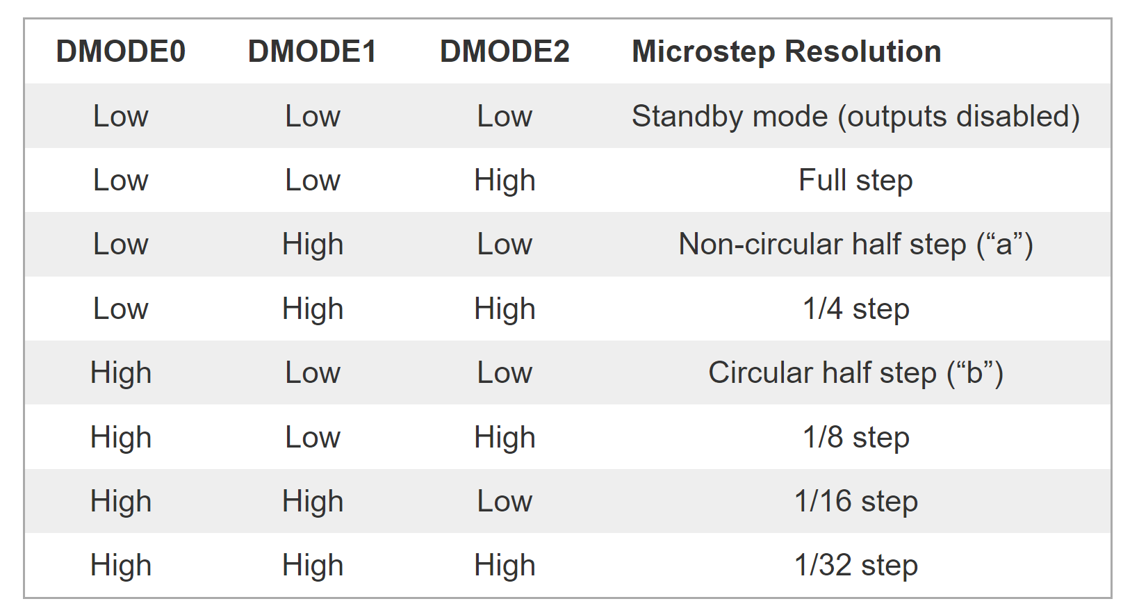
DMODE0 through DMODE2 are typically MS1 through MS3 on the stepstick. These pins are more commonly connected to jumpers rather than the controller.
TB67S249FTG example config
      stepstick:
        step_pin: I2SO.5
        direction_pin: I2SO.4
        disable_pin: I2SO.7:low
        ms1_pin: NO_PIN
        ms2_pin: NO_PIN
        ms3_pin: I2SO.6:high
        reset_pin: NO_PIN
¶ Trinamic Drivers
Trinamic drivers (TMC2130, TMC2208, TMC5160, TMC2209, TMC5160Pro/TMC2160Pro) have their own dedicated page, since there are many of them and each has its own set of config items.
¶ Other Motor Types
A few motor types have their own dedicated pages: