¶ Overview
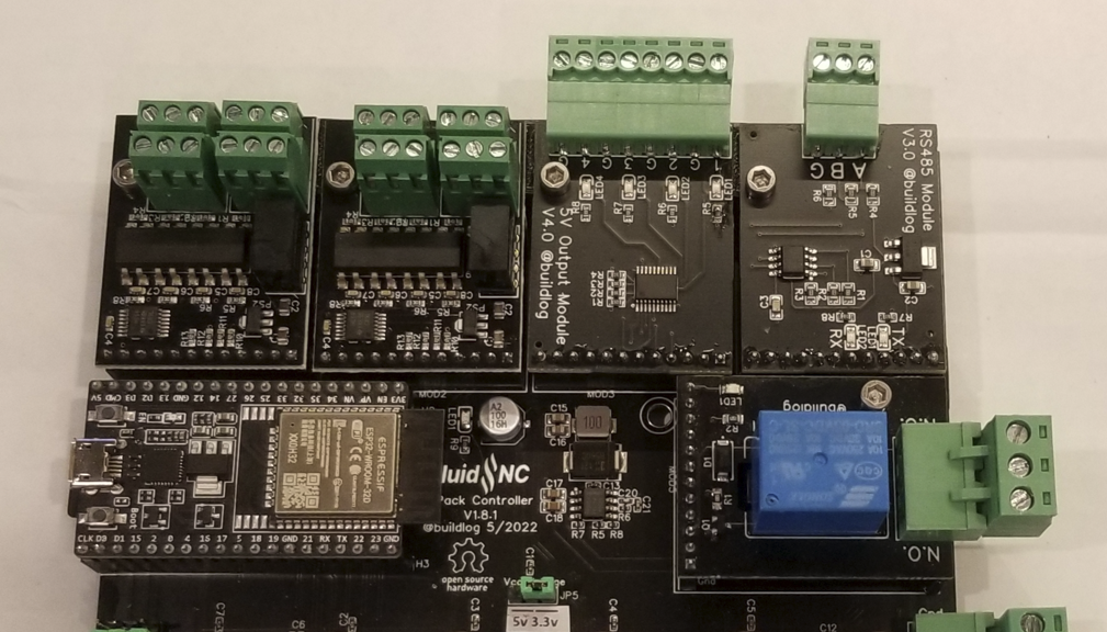
The concept started as spindle modules. I wanted a single controller to be able to support any any spindle that FluidNC supported and to be able to future proof it for any new spindles that were added to the firmware. The idea quickly grew to cover all types of inputs, outputs, displays, pendants etc.
The ESP32 microcontroller is very well suited to this idea because most periferals like, UARTs, PWMs, I2C, etc can be router to most pins.
These modules support a great variety of CNC devices. Several controllers already support them.
- 6 Pack Controller
- 6 Pack Controller for external drivers
- 6x Controller
- Jackpot controller
- Pen Laser Controller
¶ Design Spec and Guidelines
¶ Schematic
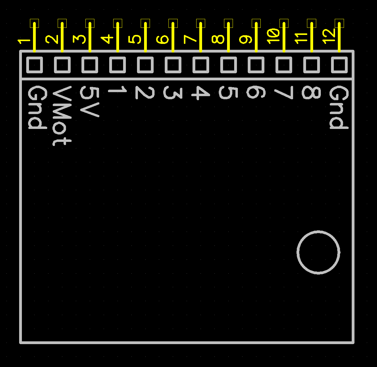
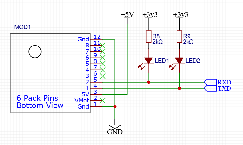
Here is the basic schematic. It has up to 4 unique I/O pins (1,2,3,4), optionally 4 shared I/O pins (5,6,7,8), Gnd, 5V and VMot. VMot is determined by the user, but is generally breater than 9V and less than 48V.
¶ Pinout guidelines
Most controllers are going to be I/O limited. They may have some GPIO, some input only and some output only pins. Some of the GPIO may be able to do PWM, I2C, etc. In order to make it easiest for controller designers to use the most possible modules, we have some guidelines on how to align the pins with the features of the module.
- Start with I/O #1 If your module is a simple relay, put the control line on this pin. If a controller designer has limited I/O signals, they could use as many single features modules as possible by many modules with signals only on I/O #1.
- Put the most desirable features first If your module controls a spindle with PWM and has a PWM output and an enable and direction output, put the PWM first.
- Put the most complex I/O requirements first Some controller pins might have some input pins, but only a few of them are also analog input pins. Putting the features with the most complex I/O requirement first may help controller designers.
- Pins 5-8 On the 6 Pack, pins 5 through 8 are being reserved for data buses, like SPI, I2C, I2S, etc. Only the first 4 pins are being used on the current modules. All of the module sockets are connected to the same 4 I/O pins on 5 through 8. Socket #4 also has those same pins doubled up on 1 through 4. This allows you to use a normal module on the pins reserved for data bus pins. If you have a special need to use more than 4 pins on a module, you can, but be aware of the impact on other modules and socket #4.
- Publish your files as open source PCBs are cheap and easy to make these days. If there is a module that is close to what you need, you can modify it and build your own.
VMot is whatever VMot is on the base controller. If you need a special voltage, like 3.3V, you will need to generate that on the board. You should pull no more than about 1 amp from either the 5V or VMot. If you need more current, you should bring that in on an edge connector.
If VMot has a range limitation, you should label that on your module or documentation.
¶ Dimensions
Here are the dimensions. The mounting hole is not connected to ground on the controller side. The side opposite the 12 pin connector is assumed to be the board edge side and should have most of the external connections.

In general you can use both sides of the board. The space between boards is about 9mm.
¶ Module pitch on motherboard
Try to put the module sockets on a 1.30" pitch. This could allow for dual wide modules in the future.
¶ Allowable alterations
- Connectors can be place on the bottom of the module. The distance to the lower board is 11mm.
- Longer Length. If need, you could go longer than the standard 42mm. This would extend the Module further over the edge of a standard controller. The user would need to deal with this length.
- Place module sockets close to the edge on controller boards. This would force the module to hang off the edge. There use would need to provide some sort of support.
¶ Existing Modules
¶ 4x Isolated Input Module
¶ Simple 2 Wire Switches
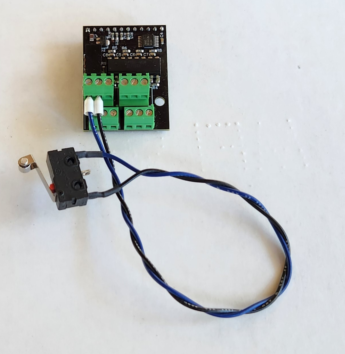
Simple 2 wire mechanical switches connect to the signal and ground pins as shown below. It does not matter which wire goes to either terminal. This will work for normally open and normally closed switches. You simply need to change the active state attribute if the switch is reporting as active when it is not (:high or :low).
¶ 3 Wire Switches
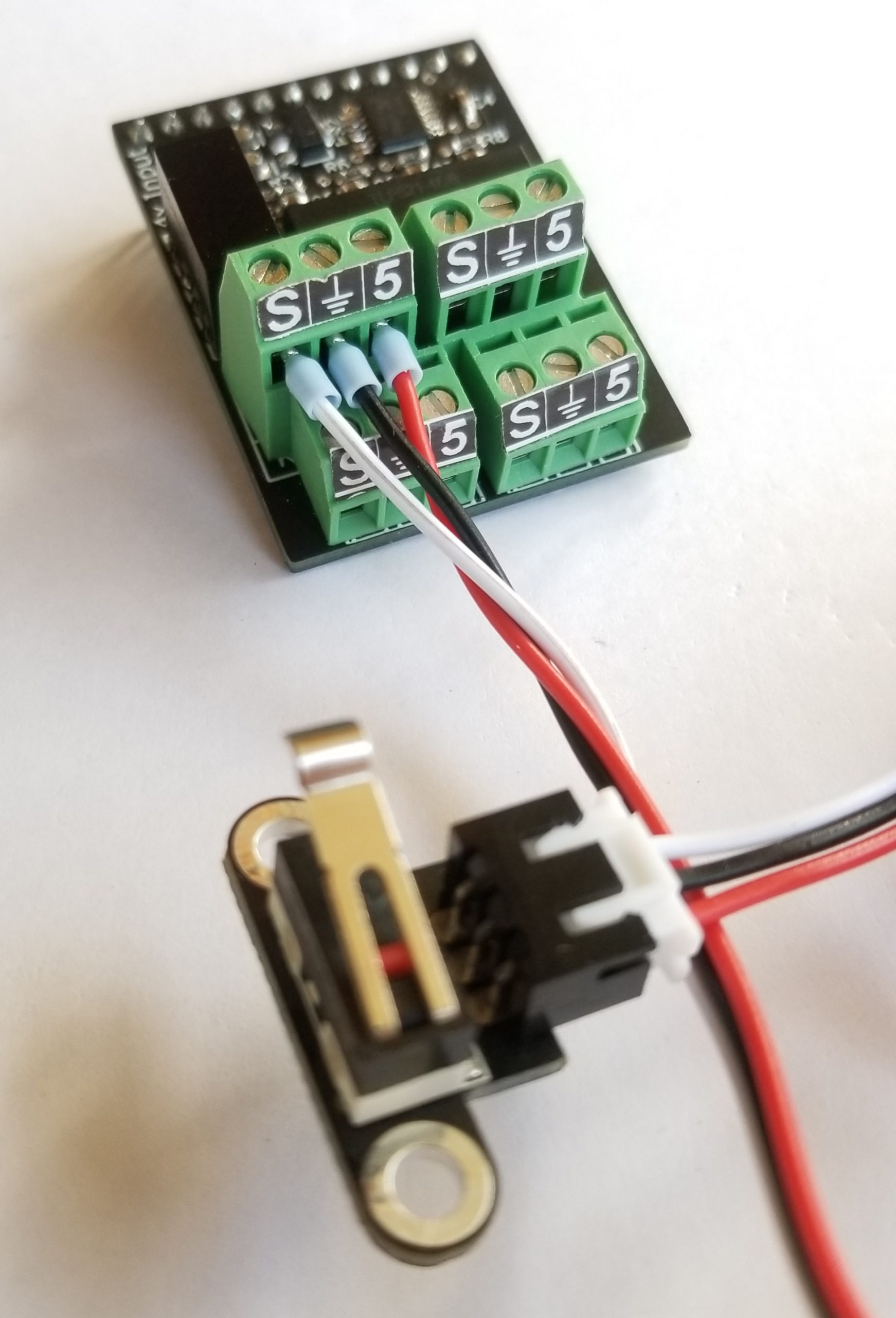
3 wire switches are common with DIY 3D printers. They are low cost and easy to wire. The 3 wires are +, gnd, and signal. The + and ground allow the switch to have an LED to indicate the state. Many are wired with a red (+), black (gnd), white (signal) color scheme. This is how they are hooked up.
¶ Proximity Switches
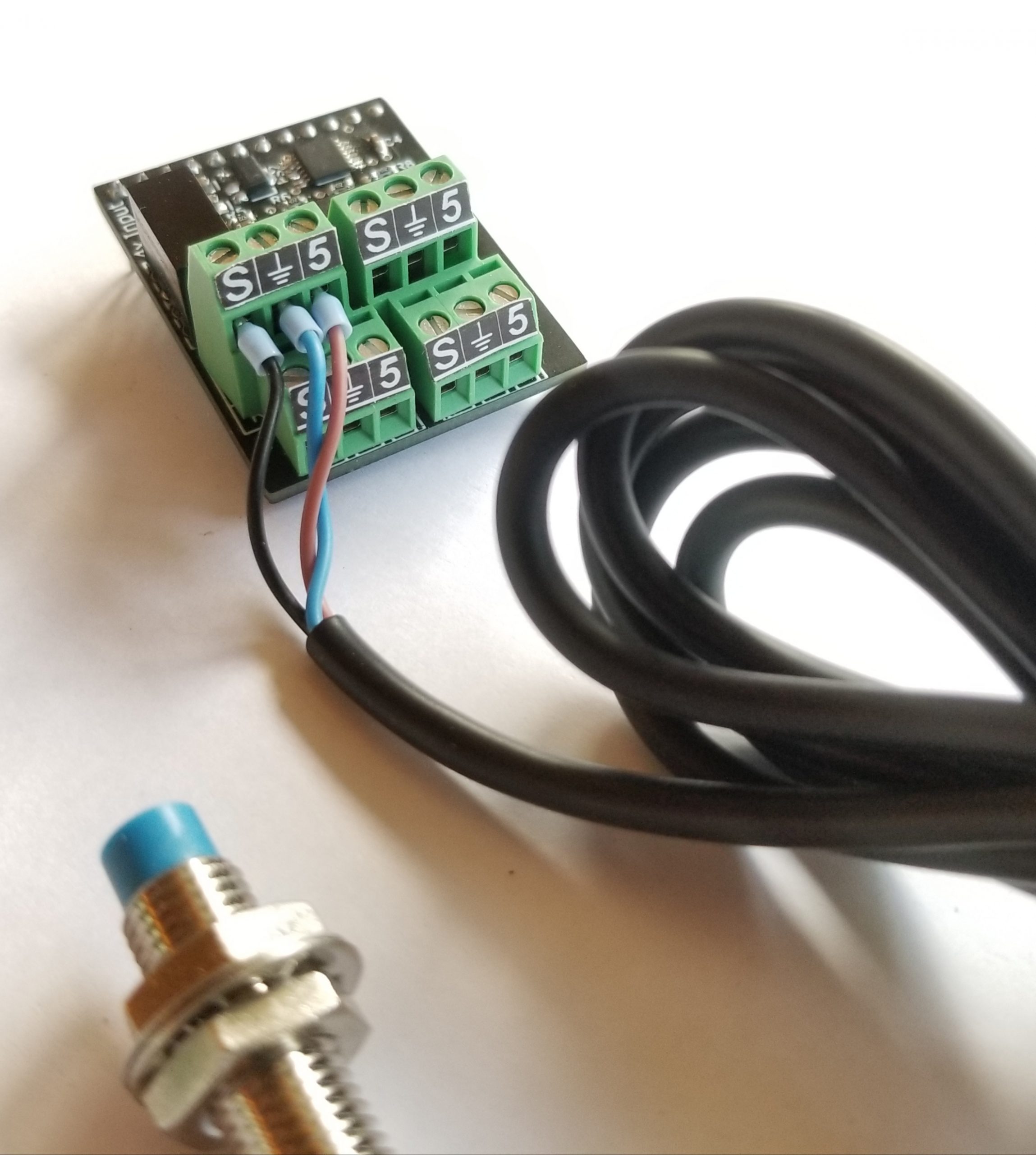
Proximity switches must be 3 wire 5V NPN type switches. Most are NPN types, but most are higher voltage with a range of 6V-30V. This module can only provide 5V. Most use the standard Blue (0V), Brown (+) and Black (Signal) wire colors. See the image for the wiring. (Twidec p/n LJ8A3-2-Z/BX-5V)
If you need a higher voltage, you need to supply that yourself. Just wire the positive side of that power supply to the sensor and connect the negative side to the input module ground terminal (center pin) along with the sensor's ground pin.
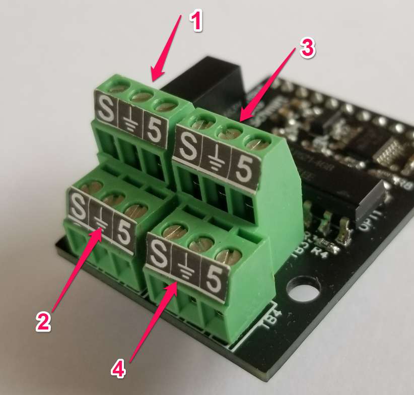
¶ How terminal blocks map to the I/O numbers
- Where to buy: Tindie
- Source Files: EasyEDA
¶ Basic Input
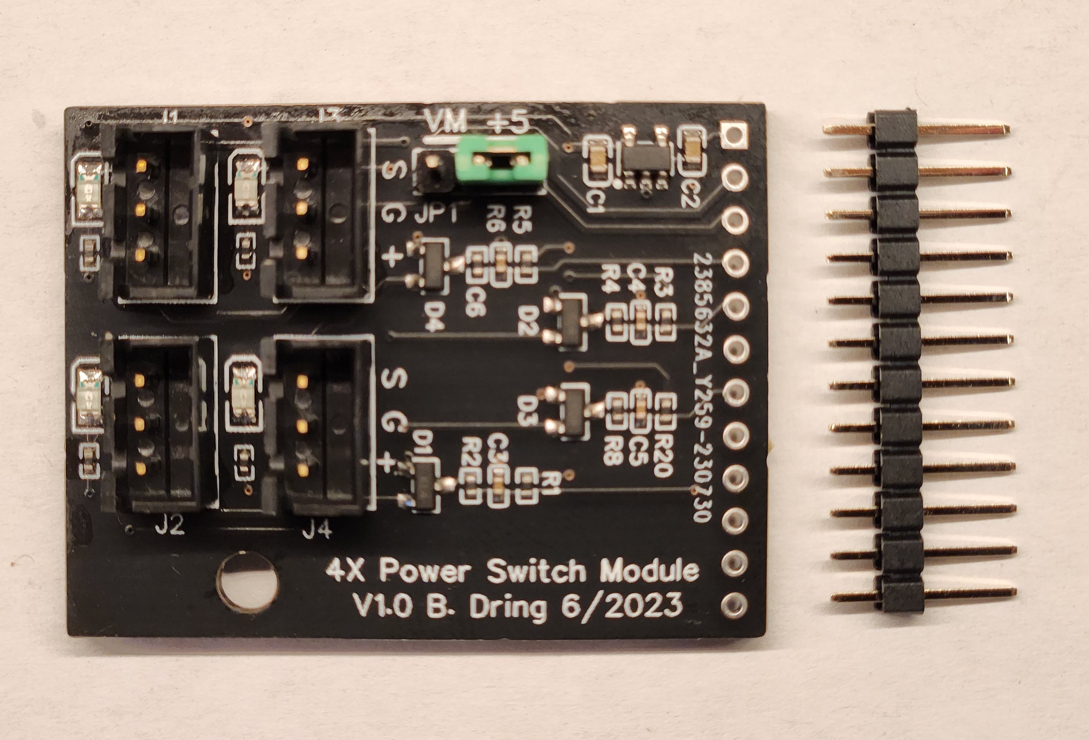
- Source Files: EasyEDA
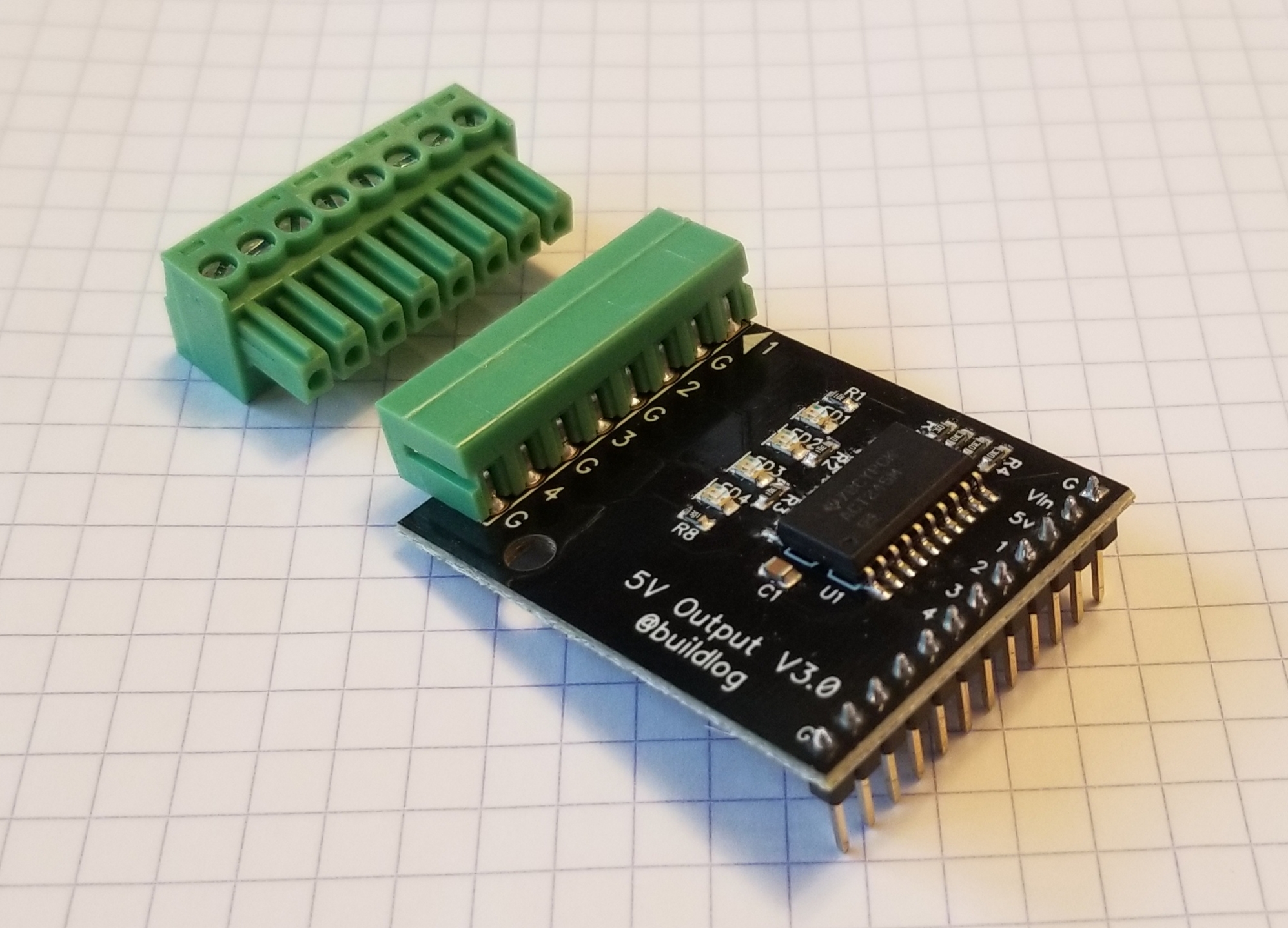
¶ 5V Output
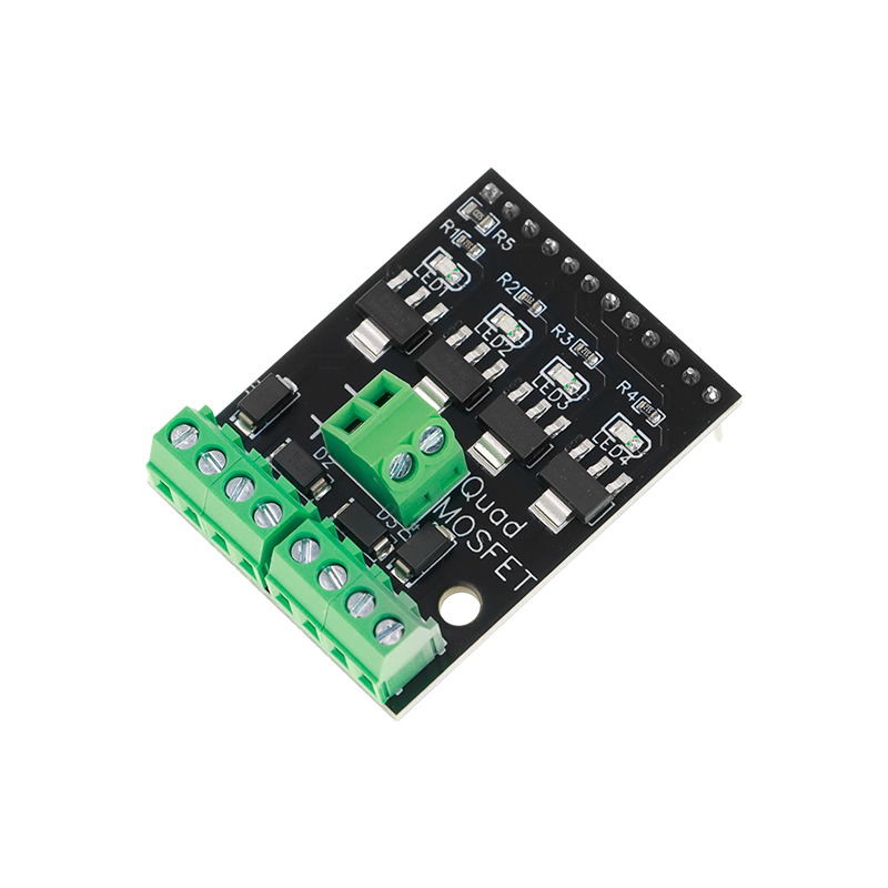
¶ MOSFET
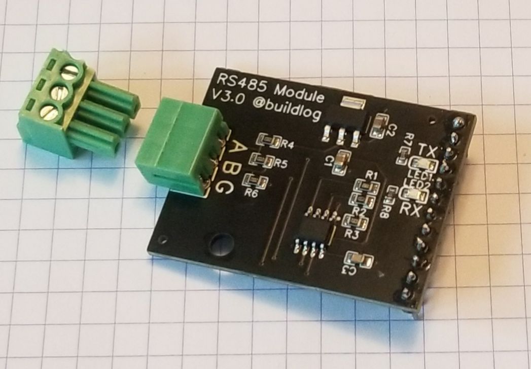
¶ RS485
This is primarily for use with VFD spindles.
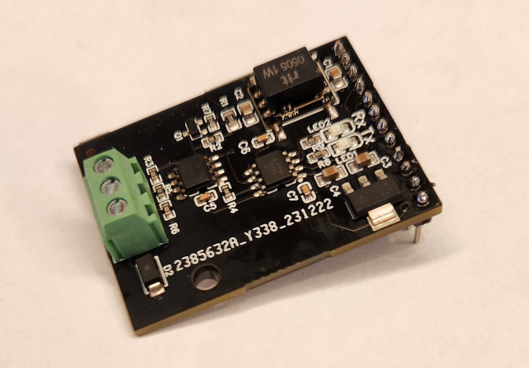
¶ Isolated RS485
This is an electrically isolated RS485 module for use with VFD spindles.
The first module i/o pin is the txd_pin
The second module i/o pin is the rxd_pin
There is no rts_pin
See the spindles page for general RS485 help
Example (Jackpot controller)
uart2:
  txd_pin: gpio.14
  rxd_pin: gpio.13
  rts_pin: NO_PIN
  baud: 9600
  mode: 8N1
¶ 10V Spindle
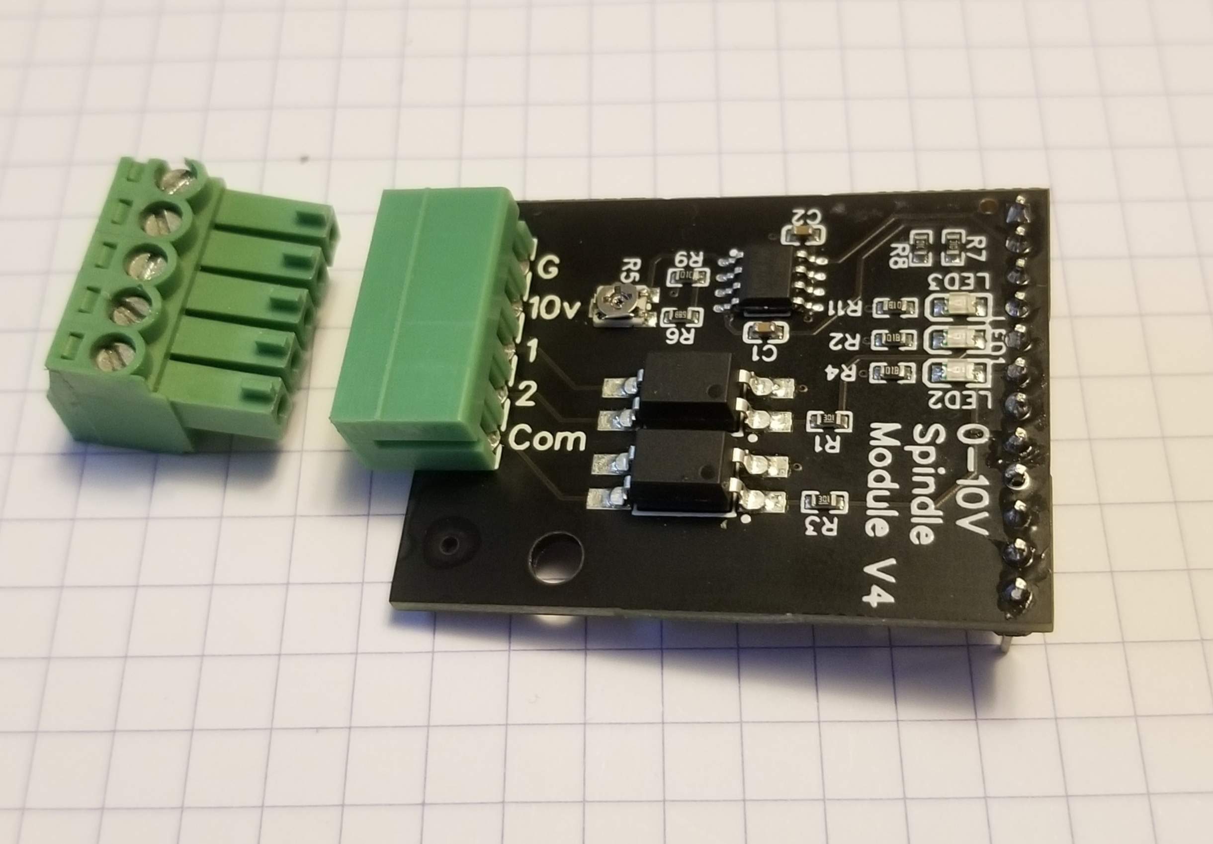
Many VFDs and other spindle speed controllers can be controlled via a 0-10v. There is a potentiometer that can adjust the output voltage so it can be used with 0-5V devices as well.
¶ Config Examples
In socket #3
10V:
  output_pin: gpio.26
  forward_pin: gpio.4
  reverse_pin: gpio.16
  spinup_ms: 0
  spindown_ms: 0
  tool_num: 0
  speed_map: 0=0% 6000=0% 24000=100%
In socket #4
10V:
  output_pin: gpio.14
  forward_pin: gpio.13
  reverse_pin: gpio.15
  spinup_ms: 0
  spindown_ms: 0
  tool_num: 0
  speed_map: 0=0% 6000=0% 24000=100%
¶ RC Servo and BESC
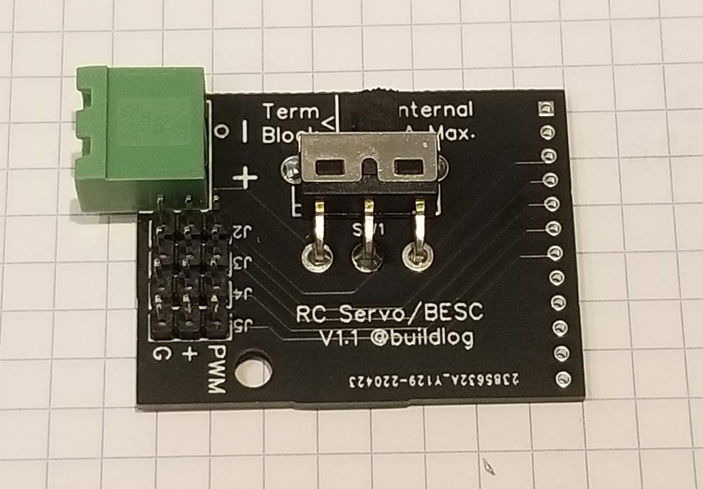
This has 4 RC servo connector. You can also use this with BESC (Brushless Electronic Speed Controller) controllers. There is a switch to select the servo power voltage from 5v to a user supplied voltage.
- Source Files: EasyEDA
¶ Relay Module
¶ Dynamixel
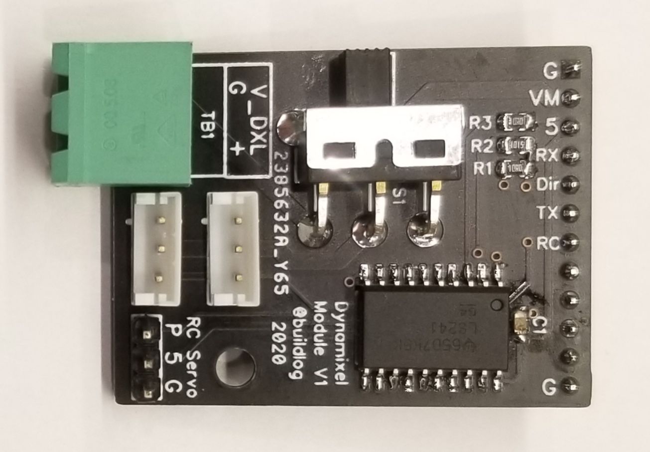
- Source Files: EasyEDA
¶ Pendant/Display Isolation Module
This protects the CNC controller from voltage spikes that come from a pendant or display that is connected by a long cord.
- Source files: EasyEDA
¶ Simple Pendant Module
This module was designed to simplify the wiring for the FluidDial Penadant using RJ12 (6 wire) cables. It also protects your controller a little by adding current limiting resistors to the UART signals and a PTC fuse to the power terminal. The PTC fuse is limited to 30V and limits the current to 200mA. You can use this with other pendants and displays as long as they operate withing the range listed above.
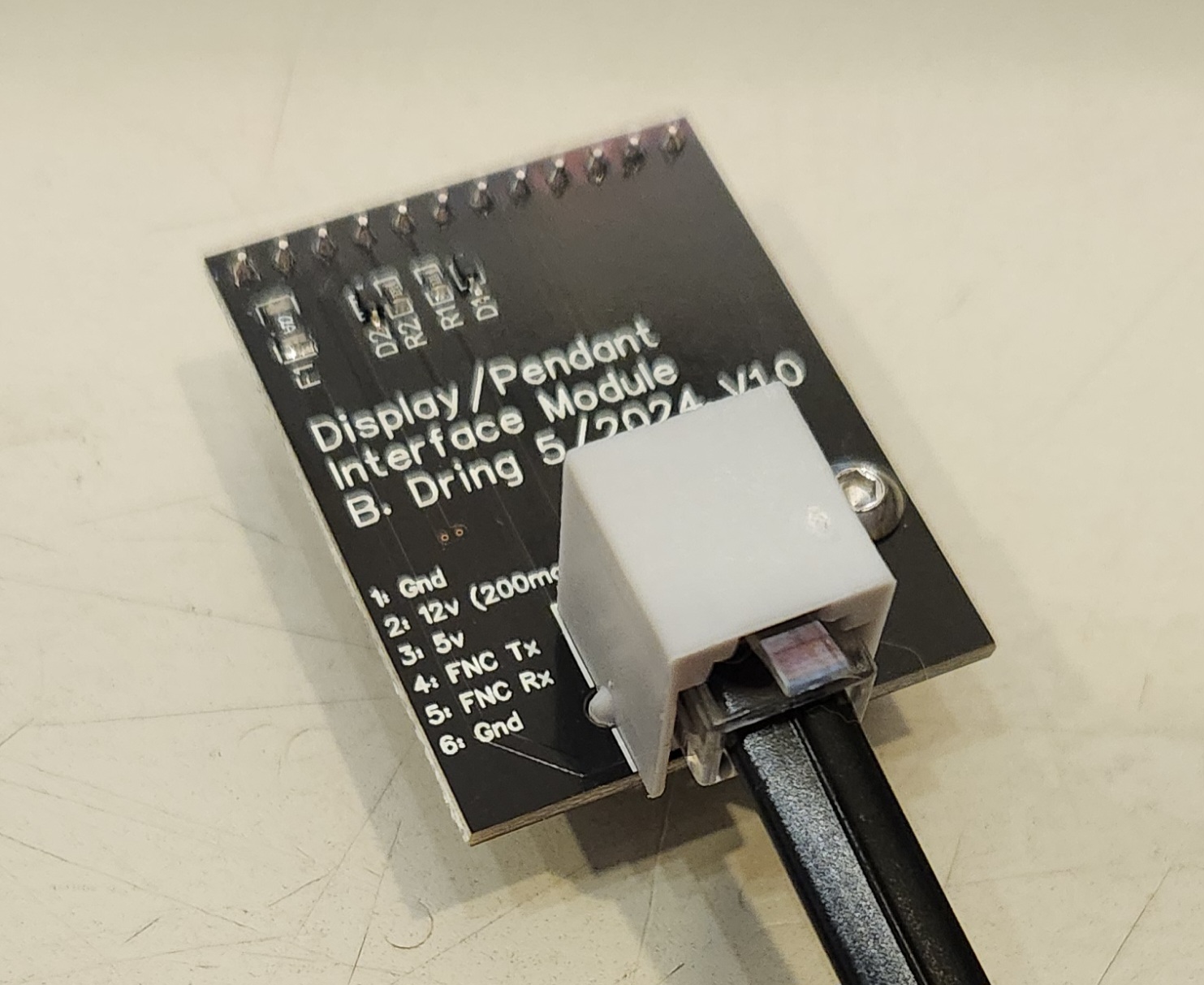
- Source Files: EasyEDA
¶ Prototype Module
This is a perfboard PCB to help with prototyping your own circuits.
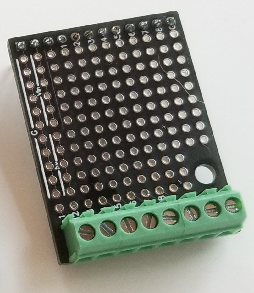
- Source Files: EasyEDA