¶ FluidDial Pendant
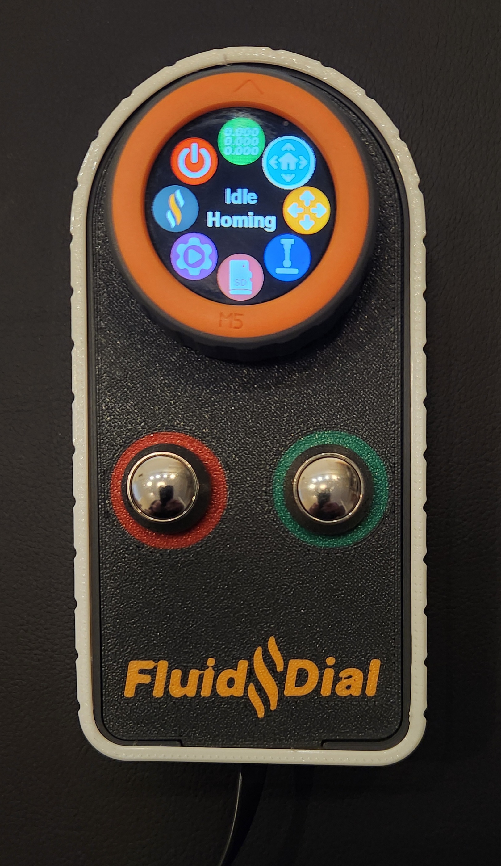
This is a very simple, but fully featured pendant using an M5Dial device from M5Stack. The goal is to make a pendant to help setup a job and monitor the progress closer to the machine than the primary control device (PC, etc).
Though FluidDial and FluidNC share primary developers, FluidDial and FluidNC are separate projects. It is intended to be a fully DIY project at this time. Nobody is selling a turnkey product. You can post support questions on Github or Discord, but the primary developers will probably let the community do the support. With that said, generous FluidNC supporters will usually get developer support.
Watch the YouTube video here. (old screens)
¶ Info & Sourcing
¶ Material Sourcing
-
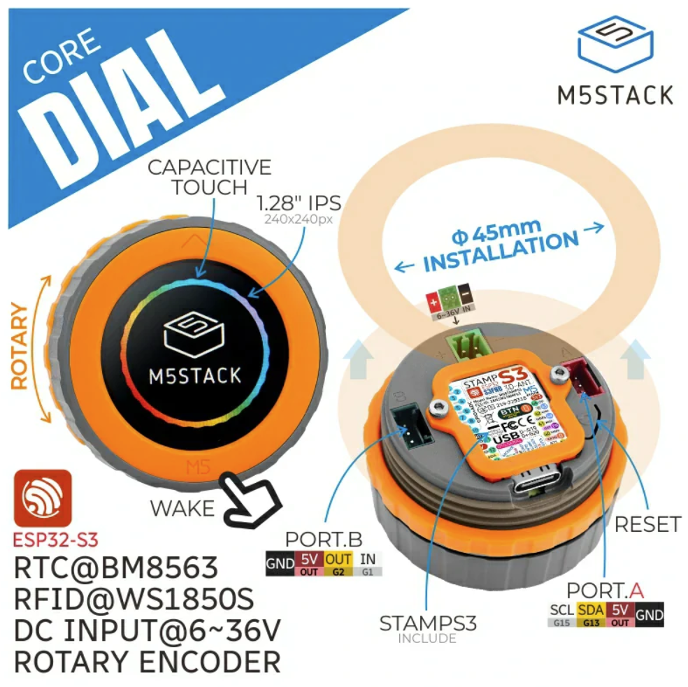
M5Dial
- M5stack.com (manufacturer's product page)
- Digikey.com
- Mouser.com
-
Ports A & B mating connectors (I think these are JST-PH connectors with a 2 mm pitch. Note: you'll need to cut the locking tabs off the white connectors to get them to plug in.)
-
Anti-Vandal Buttons (two are needed — one for red, one for green)
- Amazon.com
- Aliexpress.us (Optional: These have colored LEDs. Choose "12mm," "Momentary self-reset," and "9-30V(12V)" in both a red LED and a green LED.)
-
Cable to FluidNC (24 AWG, 4-conductor cable)
-
3D files for case and PDF for label
¶ Schematic
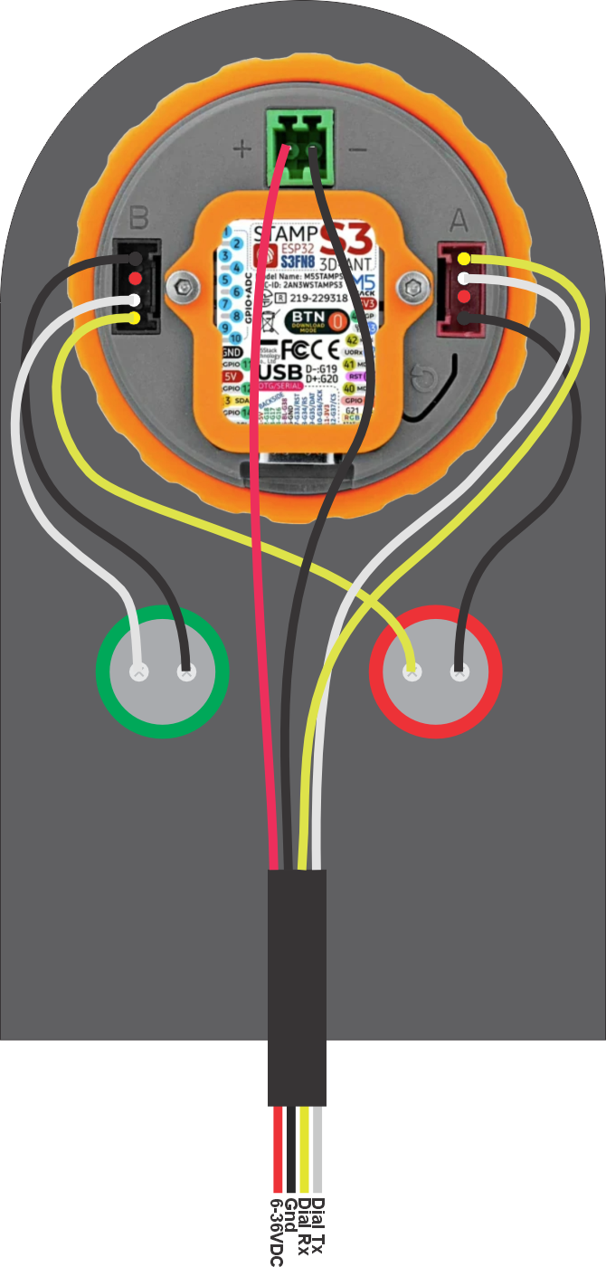
¶ Wiring
See the links above for pre-wired connectors. Due to the M5Dial enclosure design, you have to cut the locking tabs off the connectors to get them to plug in.
WARNING: If you make a mistake in wiring or with the config file you will probably break the pendant and maybe your controller. People have broken them with a simple swap of the TX and RX in the wiring or config file. Be careful and check your work multiple times. See the FAQ below on ways to repair the pendant.
¶ Installing Firmware
¶ Using The Web Installer (recommended)
Use your web browser to install the firmware. Go to the Web Installer and follow the prompts to the FluidDial (M5Dial).
¶ Using PlatformIO
¶ For the latest code you need:
Use vscode with PlatformIO to compile and upload the code
-
Source code FluidDial - main branch
-
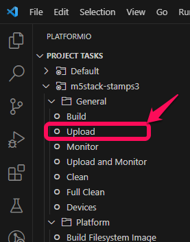
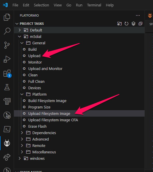
Click on the PlatformIO icon along the left side on the vscode window.
-
Open the M5Dial/General folder and click Upload to upload the firmware
¶ Upload the image files
Open the Platform folder and click on Upload Filesystem image
¶ FluidNC Config Example
You can use any 2 pins on the ESP32 that are UART capable (most are)
The default baud rate is 1000000. It can be changed in platformio.ini in this statement
-DFNC_BAUD=1000000
The config file Tx and Rx are with respect to the FluidNC. Be sure to connect the FluidNC Tx to the pendant's Rx and the FluidNC Rx to the pendant's Tx.
uart1:
  txd_pin: gpio.26
  rxd_pin: gpio.4
  rts_pin: NO_PIN
  cts_pin: NO_PIN
  baud: 1000000
  mode: 8N1

uart_channel1:
  report_interval_ms: 75
  uart_num: 1
¶ Usage (version 2.x)
¶ Menu Screen
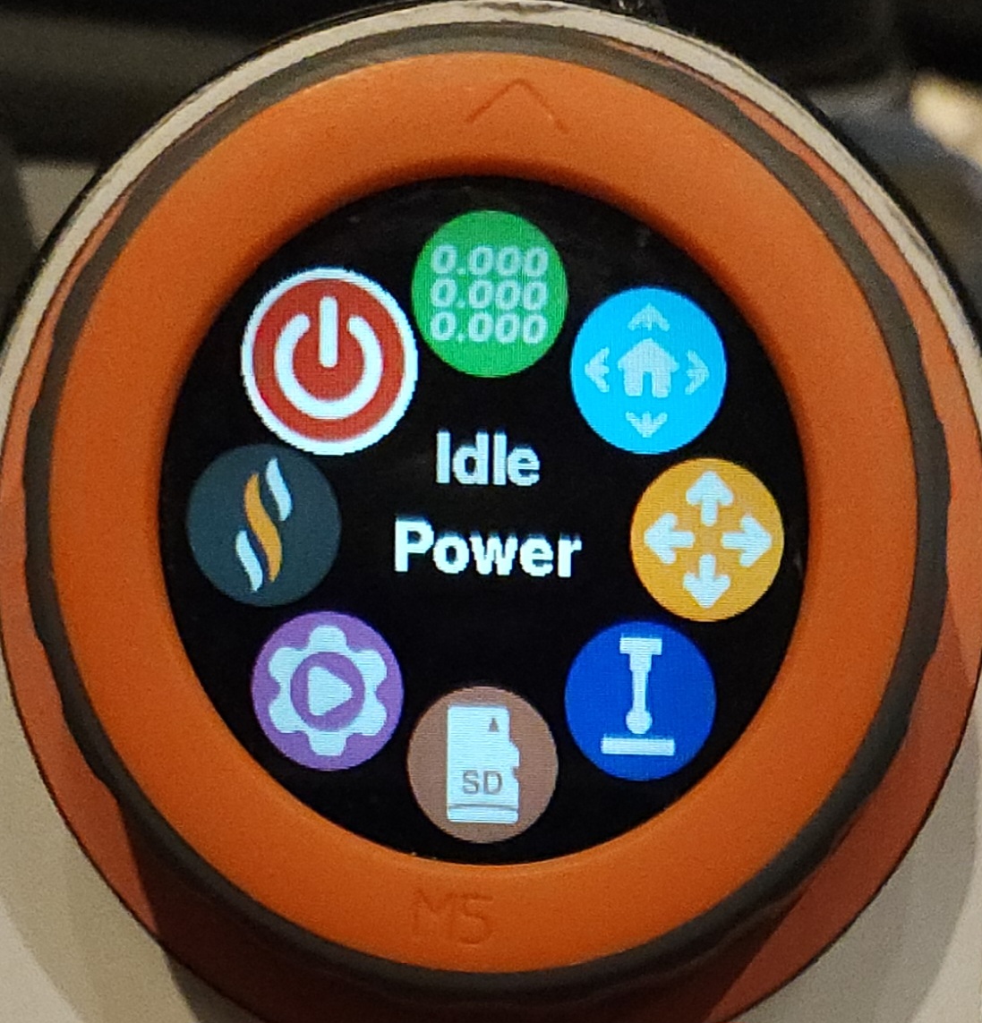
This screen allows you to navigate to all other screens. Many of the icons are disabled in the N/C state (not communicating yet). You can select a menu item by rotating the dial, then pushing the bezel button. You can also go directly to a new screen by touching the icon. A third way is to touch the center and flick your finger towards the icon.
¶ Status Screen
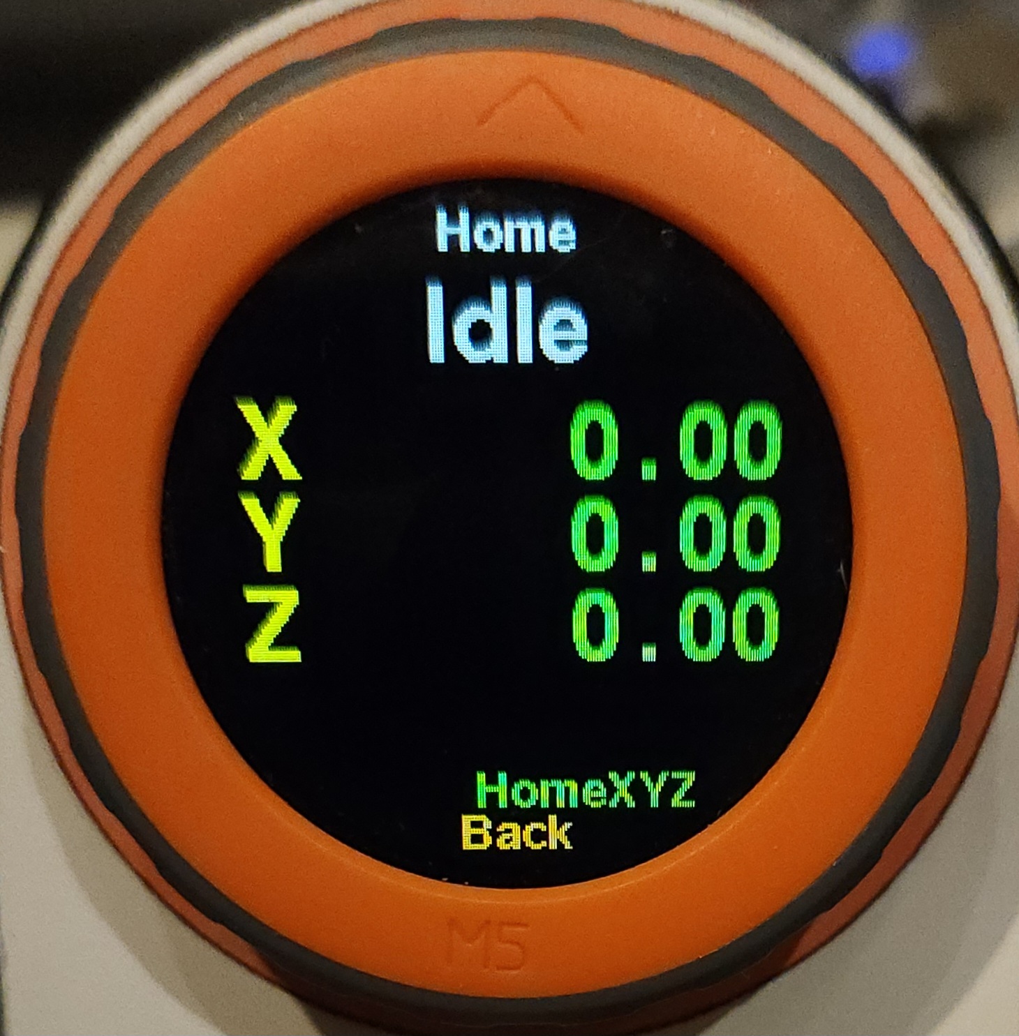
This is the screen you would normally use during a running job. It shows the current position positions of the axes and the gcode modes.
The bezel button always takes you back to the main menu. You can also touch+flick to the left to go to the menu.
The controls are based on the current state (Idle, Run, Hold, Alarm ,etc).
- Idle
- Run
- Red Button Stops the job immediately with a reset. Work position is probably lost. The spindle will turn off
- Green Button enters feedhold mode.
- Encoder Dial Turn to change the feedrate override value
- Hold
- Red Button Quits the current job
- Green button Resumes the job
- Alarm
- Home
- Red Button Cancels homing. You will be put into the alarm state.
¶ Homing Screen
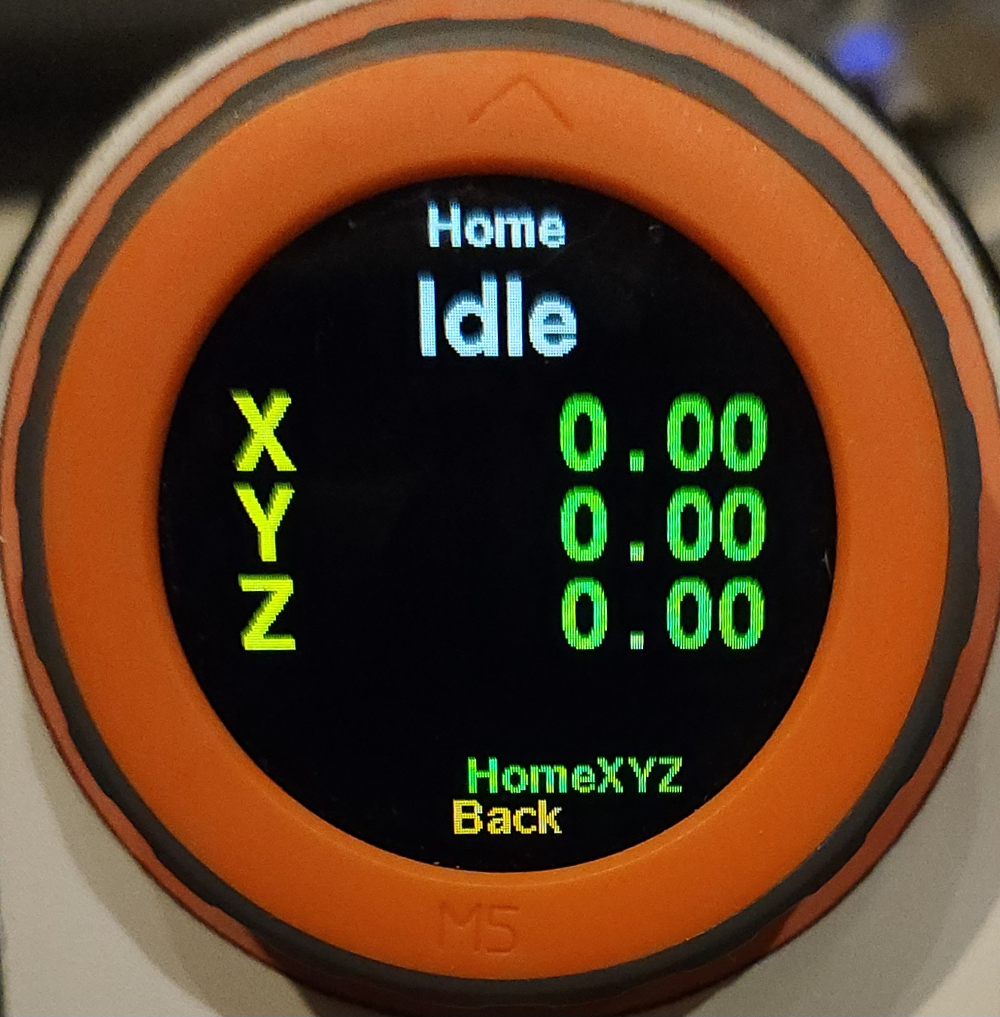
By default you start in home all mode. You can select a single axis to home by touching the screen. The axes will turn from red to green after they successfully home.
¶ Jog Screen
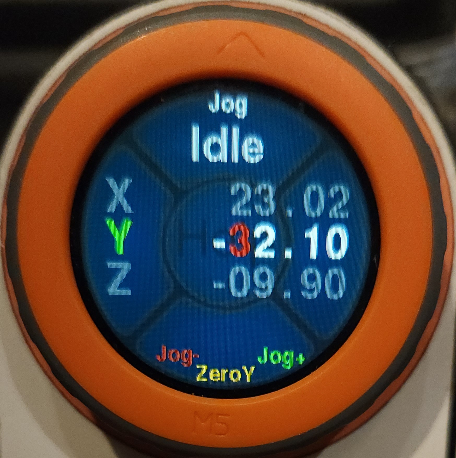
This screen allows both rotary encoder jogs and continuous jogs to be used without switching jog modes.
Touch navigation
The background of the screen shows the 5 finger touch zones in a faded blue graphic. There are 4 quadrants around the outside and a circle in the center.
- Touch the circle in the center for help using the screen
- The top and bottom touch zones cycle through the axes. The active axis will be highlighted with the axis letter in green and the digits in white.
- The left and right touch zones change the digit representing the jog amount. The digit will be highlighted in red. It represents the jog increment as well as the jog speed, which is proportional to the increment.
- To cancel an active jog, touch anywhere on the screen.
¶ Probe Screen
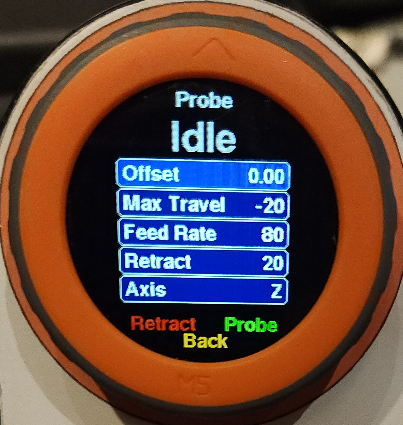
This screen is for using the probe function of FluidNC.
It has many adjustable parameters listed in blue boxes. You adjust the highlighted parameter by rotation of the dial; clockwise for positive and counterclockwise for negative. Cycle to the next parameter by tapping the screen.
In the Idle state, you can click on the retract button. It will retract in the opposite direction from the probe travel.
- Offset: Set this value if you are using a probe block or touch plate. It will compensate this amount when setting the work zero after the probe.
- Max Travel: This is the maximum distance the machine will travel to find the probe point. This value can be positive or negative. For example, most people will probe Z in the negative direction. With soft limits enabled, this value must be less than the available travel distance, or an alarm will occur.
- Feed Rate: This is the speed of the probe operation.
- Retract: This is the distance value of the retract. It is a positive number and will retract opposite of the probe direction.
- Axis: The axis you are probing.
When the probe contact is made the axis zero is set immediately. The axis then decelerates to a stop. The location when it stops is slightly past the contact point. This over travel is normal and proportional to the probing speed. Do not worry about this. The location of the touch point was accurately set. The WebUI, your gcode sender or a macro might work differently, but they all set the actual contact location the same.
¶ Files Screen
¶ Macros Screen
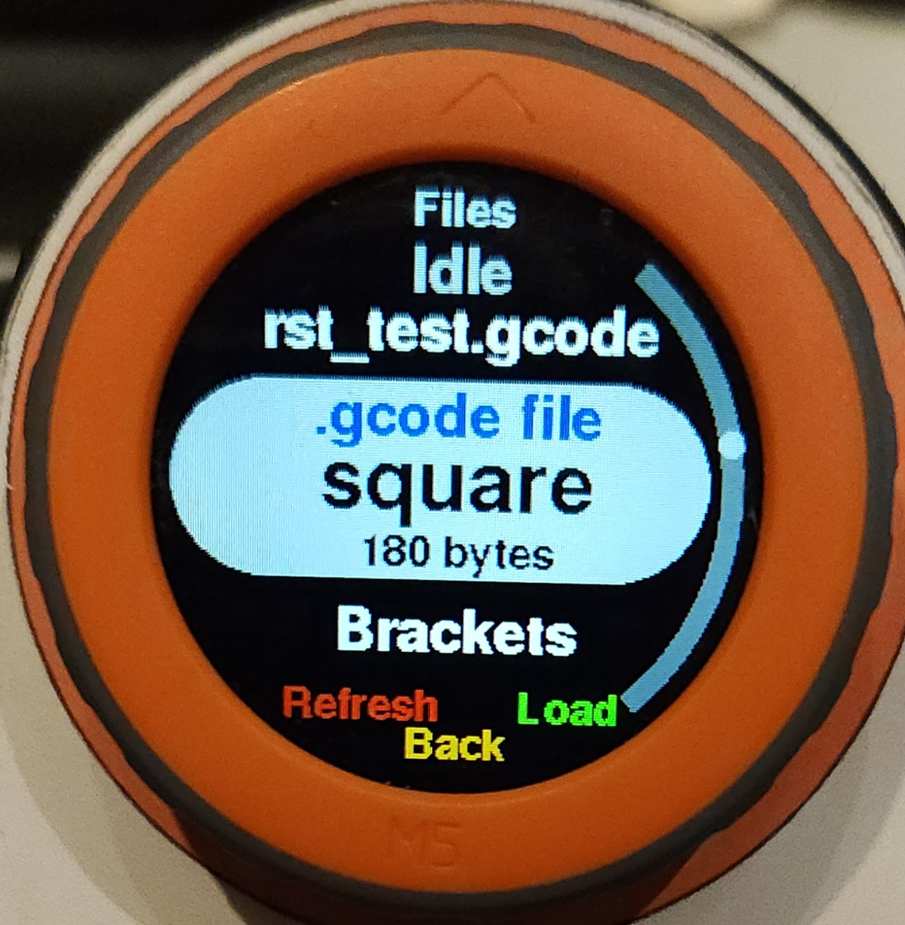
The Macros screen works very similar to the files menu except the macros are stored in flash memory rather than on the SD card. It uses the macros that the WebUI sets up. You can learn more about macros here.
If you don't have any macros setup, the screen cannot be used.
¶ About Screen
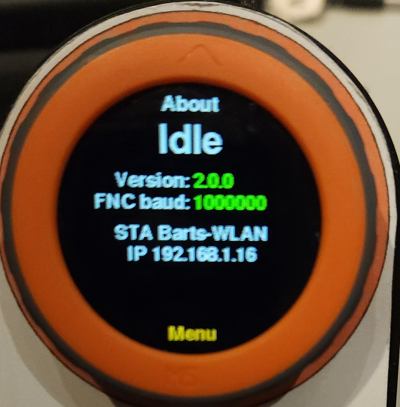
This screen gives some basic info about the FluidDial and FluidNC configuration.
¶ Power Screen
This screen allows you to power cycle the pendant or put it to sleep. Sleep is basically off, but you can restart from the red button.
¶ Connections to Controllers
¶ 6 Pack Style Module Sockets
6 pack module sockets are designed for use with 6 pack modules. The socket pins connect directly to ESP32 without protection. This allows the greatest flexibility to module functionality. The plug in modules should provide the noise and spike protection.
There is a module available on Tindie and Elecrow (see below). The 6x CNC Controller documentation covers configuring the controller and use of the module on that board.
If you want to make your own module you can do that from the source files. If you want to wire directly to the module sockets, please use good design practices in the wiring. Many people have broken the ESP32 on their controllers due to noise and ESD problems. Long cables in a noisy environment will eventually see ESD problems. If you break your controller with your custom connection to a module socket, the controller will not be replaced.
¶ Standardized connectors.
RJ12 6 Pin Socket
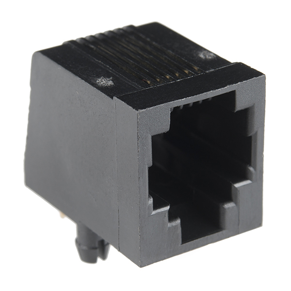
- 1 Gnd
- 2 12v - 30v (12v recommended)
- 3 5v
- 4 FNC Tx
- 5 FNC Rx
- 6 Gnd
¶ RJ12 Connectors
This is a CNC I/O module PCB with an RJ12 connector and a PCB for the FluidDial side.
The following kits are for sale:
- Tindie (US Only) Connection Starter Kit. This includes both the CNC I/O module and a wiring kit and PCB for the FluidDial side.
- Elecrow (International) 6 Pack Module and FluidDial Wiring Kit. Both combined equal the Connection Starter Kit available on Tindie.
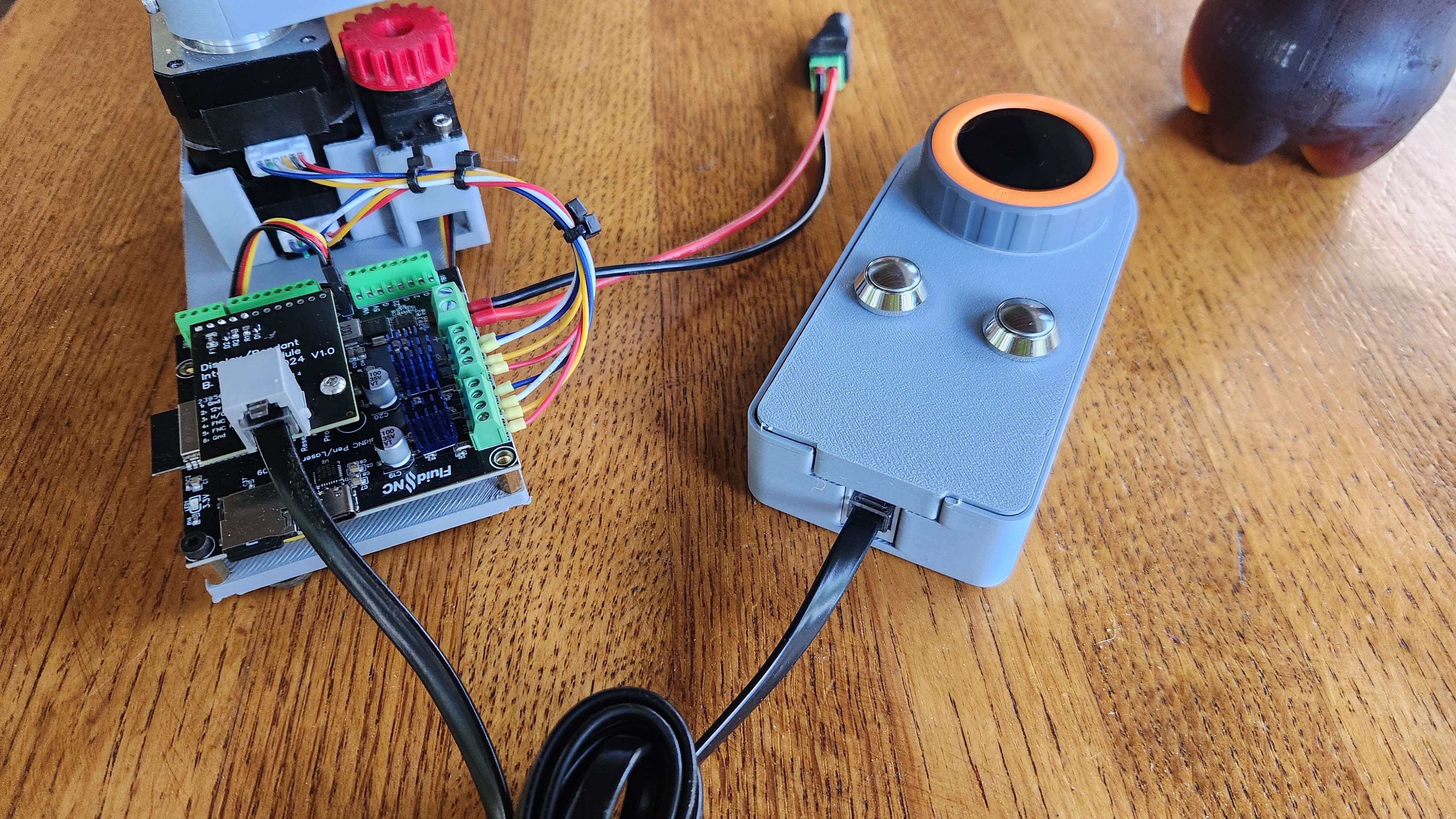
Example FluidDial connected to the connection module on a 2x controller.
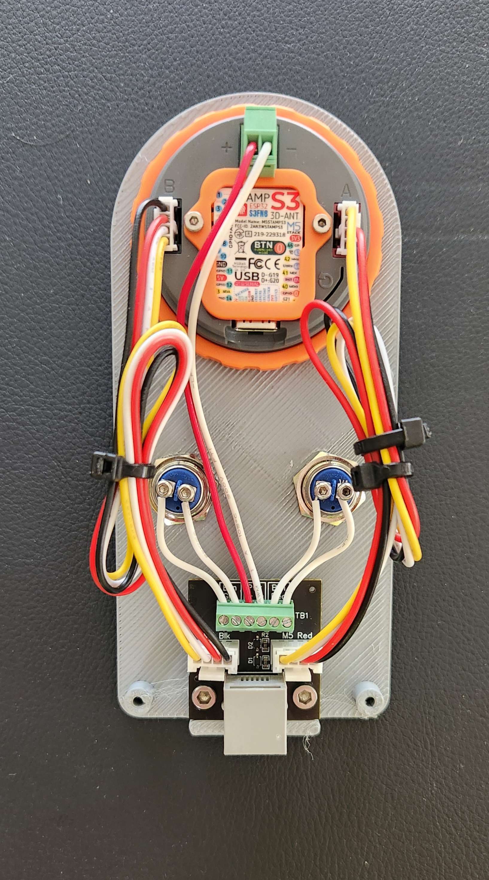
Wiring example with the wiring kit on the FluidDial.
Here are the STEP files for the enclosure.
Use 4 Pin Grove cables. 10cm to 20cm will probably work.
¶ FAQ
- There are no icons on the screen You forgot to upload the file system. Reread the instructions.
![]()
-
Firmware won't upload.
- Sometimes it gets into a funk and needs a manual bootloader activation. This usually happens if the code is continuously rebooting or stuck in a tight loop.
- Hold the Button on the M5Stamp, under the label. I removed the label to make it easier.
- Click the grey M5Dial reset button. Lower right corner of back
- Release the M5Stamp button.
- Now try to upload the firmware.
- If it uploads, you need to click the grey button again to enter run mode again.
- Sometimes it gets into a funk and needs a manual bootloader activation. This usually happens if the code is continuously rebooting or stuck in a tight loop.
-
Still having upload problems Try adding this in the [env:m5dial] section of the
platformio.inifileupload_flags=--no-stub
-
What does N/C in the status box mean? N/C means no connection. It is not receiving data correctly from FluidNC. Try tapping the screen. Many screens will attempt to refresh the status if you do this. A power off and restart might help (see power screen above)
-
Macros don't load If you get a "Reading macros" message displayed, but the macro never load, you probably have a missing or incorrect file on the FluidNC ESP32. You need a file called
macrocfg.jsonif you are using WebUI 2 orpreferences.jsonif you are using WebUI 3. Use command$Localfs/listto see the contents of the ESP32 file system. Send$localfs/show=\<filename\>to see the contents of the file. -
My saved values are messed up We have seen this during upgrades. Right now the solution is to reset them with "Erase Flash" in PlatformIO. Then reprgram the pendant.
-
Can it support more than 3 axes? No, the layout was pretty tough to fit. If you want more, fork it.
-
Can this be wireless? The M5 Stack Dial was designed to be a battery wireless interface for IOT projects. It has a battery connector and a charging circuit. It has an ultra low power sleep feature and it can wake up on demand. You do need a receiver. This could be the ESP32 FluidNC runs on, but that might conflict with your setup if you already use the wireless features for something else. So, the current answer is no, but a skilled programmed could make it happen.
-
The alarm description seems wrong. There is no way to get the last alarm number from FluidNC. The pendant has to track that itself. If the pendant was turned on late or missed the alarm message, it may not know it.
-
I think I broke my pendant, what do I do? You are not the first. This is a sensitive device with no protective circuitry. Many people have been able to repair it by swapping in a new M5 Stamp S3 (1.27mm pitch) about $8. Many local distributors also sell it. If you broke it with power wiring errors, you may have broken everything.
-
I have read the whole wiki, and I have further questions Inquire on Discord for more info.
¶ Developer Info
¶ Documentation
¶ Ports
Port A (red conn) is for the serial conn to FNC
- Black Gnd
- Red 5V (Not Used)
- White G13 UART Dial Tx
- Yellow G15 UART Dial Rx
Port B (black conn) is for the buttons
- Black Gnd
- Red 5V (Not Used)
- White G2 Green Button
- Yellow G1 Red Button
¶ Debugging
USBSerial
Some echoing and debugging info is sent over this connection. It will not normally be used. It also is an easy way to power during development.
¶ Debugging Crashes
For Developers - If the code crashes, a coredump will be created in the ESP32 FLASH. You can extract and decode it with tools from ESP-IDF.
¶ One time setup
- In VSCode, install the "Espressif IDF" extension.
- Type F1 then "ESP-IDF: Configure ESP-IDF Extension"
- In the setup screen, choose Express
- In the next screen, in "Select ESP-IDF version:" choose "v5.0.5" (other versions might work; I only tried 5.0.5
- Click the blue Install button and wait until it finishes (messages in OUTPUT) window
- Type Ctrl-E T to get the terminal.
(Alternative: it is also possible to do it from a CMD window without VSCode; download ESP-IDF and run install.bat then export.bat.)
¶ Getting a crash dump
- In the terminal window, make sure you are in the top level build directory for the pendant app, for example M5Dial_Scenes
esp-coredump.exe --port COM18 --baud 921600 info_corefile .\.pio\build\m5stack-stamps3\firmware.elf
Replace COM18 with the port connected to your pendant debug port. If you don't have any other ESP32s connected, it might be possible to omit the port argument.
If all goes well, you will get a lot of debugging info about what was happening when the crash occurred.
¶ Debugging
If you connect a terminal to the USB port (any baud) you will get a lot of realtime debugging information.
¶ Connection Problems
This is a partial list of things that could prevent FluidDial from connecting with FluidNC
- Bad physical connection - broken wire or connector pin
- Rx and Tx lines swapped
- UART connected to wrong port on M5Dial - The port you use must match the UART_ON_PORT_B setting in Config.h
- Wrong uartN: and/or uart_channelN: configuration in the FluidNC YAML config file
- Wrong baud rate - the baud setting in uartN: section of the config file must match the baud rate that is established by the FluidDial code.
- Connected to wrong ESP32 pins on FluidNC controller.
- Using a version of FluidNC that does not support the version of the FluidDial code you are using.