¶ FluidNC Controller Design Best Practices
¶ ESP32
The ESP32 must be the dual core 240MHz version. See this page for details. Any memory size above 4Meg will work. Currently the pre-compiled version will only use 4Meg. The rest of the memory will not be accessible unless you compile yourself with a custom partition. Ask on discord about this.
¶ Module vs. Devkit.
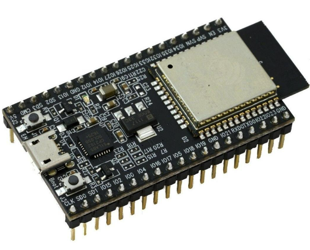
The DevKit mounted in a socket is recommended for first time controller designers. It is cheap and easy to replace. The module is complicated and very layout sensitive.
¶ Module layout guidelines
Typically the antenna should hang over the edge of the board. If it must be on the PCB be sure there is no copper under the antenna section by as wide a margin as possible.
The USB connections (D- and D+) to the USB/Serial chip should be as short as possible and equal lengths.
¶ Boot and Reset buttons
These are handy if the USB is having trouble triggering bootload mode. The official Espressive Dev Kit schematics are a good design reference.
Also see this page for detailed information.
¶ Antennas

The built in PCB antenna of standard modules is generally good enough. It is usually on a black pcb that hangs off the back of the module. If you want to use this type be sure you leave room for the antenna and do no not place any large components under it.

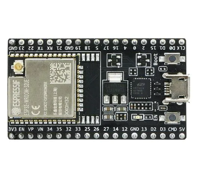
If you need more range, you can get a module with a connector for an external antenna. The modules typically have a "U" in the part number, like ESP32-DevKitC-32UE.
The antenna connector is usually an IPEX type. You need an adapter cable to something larger like an SMA connector for the antenna.

¶ 5V
Be careful that the USB 5V is not overloaded. Consider a diode that allows the main 5V to power the ESP32, but the USB cannot power the rest of the controller.
The ESP32 can pull spikes of current when turning on the radios. Be sure to add some capacitance on the 5V or 3.3V near the ESP32.
¶ 3.3V
If you are using the 3.3V from the DevKit, be careful not to overload it. It comes from a 3.3V LDO. Only use a few milliamps for things like pullups. If you need more, you should use a separate source.
¶ GPIO Pins
Be sure to check these pin guidelines before starting. It is everything we know about the ESP32. There are other issues, so check ESP32 documentation too. Pay special attention to the turn on conditions of the pins. An external pullup on the wrong pin can prevent proper booting or damage the ESP32.
Create a chart of all the functions you want and map them to the pins.
¶ IS2O Output Expansion
ESP32 has too few GPIO pins to make complex controllers. With GPIO, you can barely make a 4-stepper-motor controller and then there are few GPIOs left over for limits, probes, spindle control, input switches, etc. Conventional I/O Expansion chips like those that are controlled via I2C are too slow for stepping, and very difficult to synchronize across multiple chips. I2S is a bus that is normally used for audio codecs, but it turns out to have characteristics that make it suitable for output expansion, especially for driving a group of stepper motors. You can "listen" to I2S with a daisy-chain of inexpensive shift register chips, providing up to 32 extra output bits at low cost. The ESP32 has an I2S hardware engine that can connect directly to the shift register daisy chain, using 3 GPIOs. The I2S engine continually sends a serial bitstream into the shift registers, then every 32 bits it sends a signal that makes the shift registers transfer the new data into their output latches where the data is held until the next latch pulse. The data is shifted at 16 Mhz and latched at 500 kHz. Since each step pulse needs a high and low phase, the max stepping rate with I2S is 250 kHZ.
People often ask if would be possible to use I2S for input expansion too. The short answer is no; the slightly longer answer is that it would in principle be possible, but there are much better approaches.
¶ I2SO Configuration.
You must define the pins to use in your config file like this.
i2so:
  bck_pin: gpio.22
  data_pin: gpio.21
  ws_pin: gpio.17
¶ IS2O Chips
The firmware is designed for 74AHCT595 chips. The "T" is important if you want TTL compatibility. The AHCT595 were chosen for the following reasons:
'595 instead of '194 because the former has holding registers after the shift registers. Without holding registers, as data is being shifted in, each output will cycle through the bits for all of the channels. That will not work at all. With holding registers, the shifted-in data is transferred to the holding register once during the N-bit shift cycle, so the final outputs see only the bits for their respective channels.
AHCT because we wanted to be able to use optocoupled external stepper drivers at 5V drive. You can usually drive their optocouplers at 3.3V but in some cases it is not really in spec and you might have to run a little slower to make them work. With HC logic, the input threshold scales with the supply voltage and Vin high is usually 0.7 x VDD, At 5V VDD, the high input thresholds is 3.5V, higher than the 3V3 outputs from the ESP32. AHCT logic has TTL input thresholds, basically 1.7V, independent of supply voltage, so 3V3 ESP32 output are guaranteed to drive it.
If you use HC at 3V3 supply:
- The ESP32 will drive it, no questions asked.
- The outputs will definitely drive stepsticks and other on-board stepper driver chips
- The outputs will probably drive external stepper drivers but some might not meet worst case specs (or you could use external buffers)
The I2S engine in the ESP32 can send either 16 bit frames or 32 bit frames. If the total number of shift register bits matches the frame size, the bits will exactly fill the shift registers. If there are more shift register bits than the frame size, the extra SR bits at the end will get old data from the previous frame. If there are fewer SR bits than the frame size, the extra bits in the frame will be shifted out into nowhere. This means you should only use 2 or 4 chips.
If you use HC at 5V supply
- The ESP32 might drive it sometimes, but the noise margin, timing, and reliability will be degraded
- The outputs will drive both stepsticks (with Vdd at 5V) and external drivers within spec
Startup States
I have not found good documentation on this, but often I seen outputs turn on while the firmware boots. This is typically fraction of a second. A pull down on the I2S_BCK line appears to help but is not foolproof. Be careful about what you control with this outputs.
Background of the I2SO
To our knowledge the technique first appeared as an esp32 controller for 3D Printers. It was then adapted for the Creality Ender 3 ESP32 Board. Next Mitch Bradley integrated the concept into his own controller and then worked with Michiyasu Odaki to adapt Simon Jouet's Marlin driver to work with Grbl_Esp32. It was a success, resulting in the 6-pack board which was adaptable to many different use cases. Prior to 6-pack, ESP32 GPIO limitations required many different custom boards for different use cases. Others have since used the core design for their own boards, including MKS DLC32 and Tinybee.
¶ Inputs
¶ Voltage
The ESP32 is a 3.3V part. Do not input 5V to the gpio or it will eventually break.
¶ Pulling Resistors
Pins 36 through 39 do not have internal pull up or pull down capability. You should add them to your controller. The internal pulling resistors, where they do exist. are quite high. You may want to add 5k-10k of additional external pullups. (carefully: See pin details above)
¶ Electrical debouncing, noise and spikes
There is no firmware debouncing at this time. Controllers should have have circuits to mitigate noise on all inputs. A simple R/C filter usually does it, but adding Schmitt triggers or optos can help as well.
If you use switches that close to ground in a normally closed (N.C.) arrangement that can be more robust to noise. The connection to ground will have a much lower impedance than a pull up and the noise will have a harder time affecting the signal. A normally closed closed limit switch is also fail safe. A break in the circuit will immediately be noticed with hard limits or before a homing attempt.
¶ Outputs
¶ RS485
We have found that the RS485 connections to VFDs are very sensitive to signal biasing. See this wiki page for more information.
¶ Connection Labeling
Rather than labeling things like output 1 or mist, consider using the actual IO pin number.
Consider labeling axes as motor numbers. You don't know if someone will use them XYZA or XYYZ
¶ TMC2209 Modules
Most stepstick format modules designed for UART use assume there is a separate UART for each module. They have a pull down resistor on the PDN_UART (Powerdown and UART) pin. If you put all modules on the same UART, you will probably need to remove the resistors. See this thread.
¶ Layout Issue Hall of Shame
- gpio.2 Pull up prevents programming of ESP32
- gpio.12 Pull up changes voltage of flash. Cannot be programmed and crashes existing firmware