¶ Overview
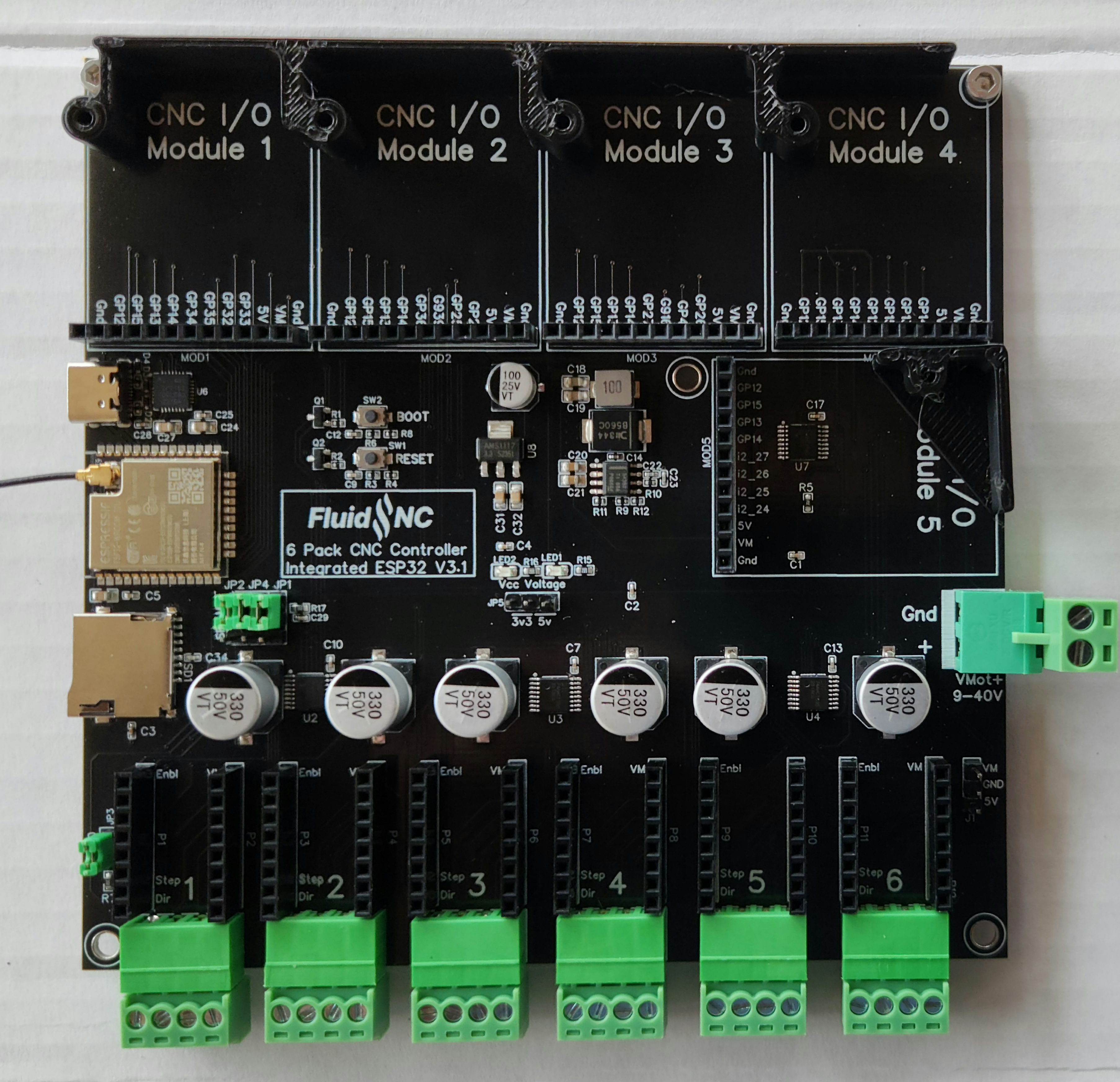
This is a version of the popular 6 Pack CNC Controller that has an integrated ESP32. The 6 Pack is designed for people who want the highest level of flexibily in their controller. Your controller can evolve over time as your machine changes.
¶ Features
- Integrated ESP32 chip
- Micro SD Card
- USB-C Interface
- 12V-40V Compatible
- (6) Motor Sockets
- Several Stepper Driver options
- Stepstick (old school, not setup by firmware)
- SPI controlled (TMC2130 & TMC5160)
- High Current External Drivers
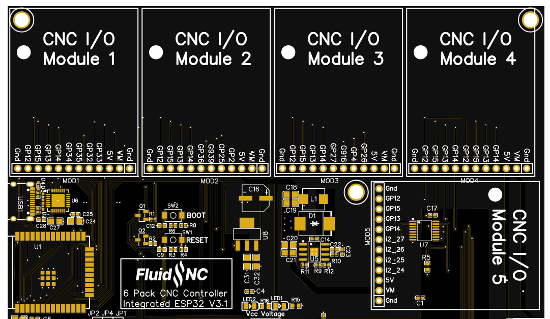
- (5) CNC I/O Module Sockets
¶ Setup
¶ Installing Modules
See this page for a list of modules
Never install modules with power on. This could damage the modules and controller.
It is extremely important that you install the modules correctly. Installing a module backwards to offset by a pin will likely destroy the module and the controller. Double check this before applying power.
¶ Power
Use a 12VDC-40VDC power supply with a minimum of 5A. Add the run current for each stepper motor to the 5A to get the total recommended current. This voltage is often refered to as VMot (Motor Voltage) in the documentation and schematic.
¶ 5V power supply
Do not pull more than 2A from the power supply for fans or other items.
¶ Fan Connector
There is a connector on the lower right that has access to VMot and 5V. This is always on and cannot be controlled via firmware.
¶ ESP32 Chip
The ESP32 chip is a ESP32-WROOM-32E-N4 (PCB antenna, 4 meg) or ESP32-WROOM-32U-N4 (Antenna connector, 4 meg)
Use an antenna with an IPEX connector.
¶ Boot and Reset Switches
The reset button reboots the controller. If you hold down the boot button when the controller resets, you will enter bootloader mode. In general the installer programs will automatically trigger the bootloader mode. You should normally not have to use the boot button.
If you are having trouble loading firmware, check to see if anything is holding gpio.2 high. gpio.2 is used on CNC I/O Module socket #2. If that is used as an input check the switch state or remove the module until the firmware is loaded.
¶ USB
The interface is a USB-C cnnector. It uses a Silicon Labs CP2102 USB to UART chip. The chip is powered by the controller power, not the USB cable, so you must have main power on to connect.
¶ Micro SD Card
The SD card uses the same SPI interface as SPI stepper drivers.
If you are using SPI stepper motors, you should lower the frequency to 400000 Hz. Otherwise you are likely to have read issues.
sdcard:
  cs_pin: gpio.5
  card_detect_pin: NO_PIN
  frequency_hz: 400000
¶ Jumpers
There are 3 jumpers that must be set.
- Vcc Voltage This jumper sets the Vcc voltage for the I2SO pins. These are used for the stepper motors. You must sit it to 3.3v for SPI type motors drivers like TMC2130 and TMC5160. You should set it to 5v for all other drivers types including external drivers.
- SPI/MS This set of 3 jumpers should all be set to SPI for TMC2130 and TMC5160 drivers. You should set it to MS (microstep pins) for all other drivers types including external drivers.
- 5160 Use the jumper for TMC5160 drivers. Do not connect it for all other drivers types including external drivers.
¶ Programming
You can program using the Web Installer or the release packages. It you buy it from Tindie it will be pre-programed and have a generic config file.
¶ Config file
All original 6 pack config files are compatible, so any examples of that will work.
¶ Stepper motor sockets
Be sure to install the modules correctly. A few pins are labeled on the sockets. Match these pins labels with the ones on the modules you are installing. Double check before applying power.
Here is the pinout for the pins that are used in your config file.
Note: Replace ms3_pin: with cs_pin: for use with SPI stepper drivers.
        # motor 1
        ms3_pin: i2so.3
        step_pin: I2SO.2
        direction_pin: I2SO.1
        disable_pin: I2SO.0

      # motor 2
        ms3_pin: i2so.6
        step_pin: I2SO.5
        direction_pin: I2SO.4
        disable_pin: I2SO.7

      # motor 3
        ms3_pin: i2so.11
        step_pin: I2SO.10
        direction_pin: I2SO.9
        disable_pin: I2SO.8

      # motor 4
        cs_pin: i2so.14
        step_pin: I2SO.13
        direction_pin: I2SO.12
        disable_pin: I2SO.15

      # motor 5
        cs_pin: i2so.19
        step_pin: I2SO.18
        direction_pin: I2SO.17
        disable_pin: I2SO.16

      # motor 6
        cs_pin: i2so.22
        step_pin: I2SO.21
        direction_pin: I2SO.20
        disable_pin: I2SO.23
¶ Stepstick
To allow the socket to be used for multiple stepper types some of the microstep selection pins had to be hardwired to to Vcc. You can only control the third microstep selection pin. This meeans you can only use (high, high, low) and (high, high, high) microstepping. On DRV8825 drivers, for example, this would be 1/8 or 1/32 microstepping. Use the MS3_pin value in your config file for this.
      stepstick:
        step_pin: I2SO.2
        direction_pin: I2SO.1
        disable_pin: I2SO.0
        ms3_pin: I2SO.3
¶ SPI Drivers TMC2130 and TMC5160
Do not mix SPI drivers with other tpes of stepstick drivers. It is OK to use SPI drivers with external drivers (standard_stepper)
¶ Using Stallguard
You must use a jumper wire to go from the diag pin on the stepper driver to an input CNC I/O module.
¶ External Drivers
External drivers can be used by placing external driver adapter PCBs in the sockets.
¶ UART Controlled Drivers are not supported
Drivers like TMC2209 are not supported in UART control mode. It was impossible to have one socket support everything. Also the TMC2209 addressing is limited to 4 chips, unless you add additional multiplexing chips.
¶ CNC I/O Modules
There is a list of modules here.
Socket 5 uses I2SO pins, so it is limited to digital (on/off) control only.
¶ Socket Pin Numbering

¶ Open Source
The design is fully open source. It can be cloned and editted with free software. There is a "one-click" ordering feature if you want to manufactured by JLCPCB.
- Source Files at EasyEDA