¶ CYD Dial Pendant
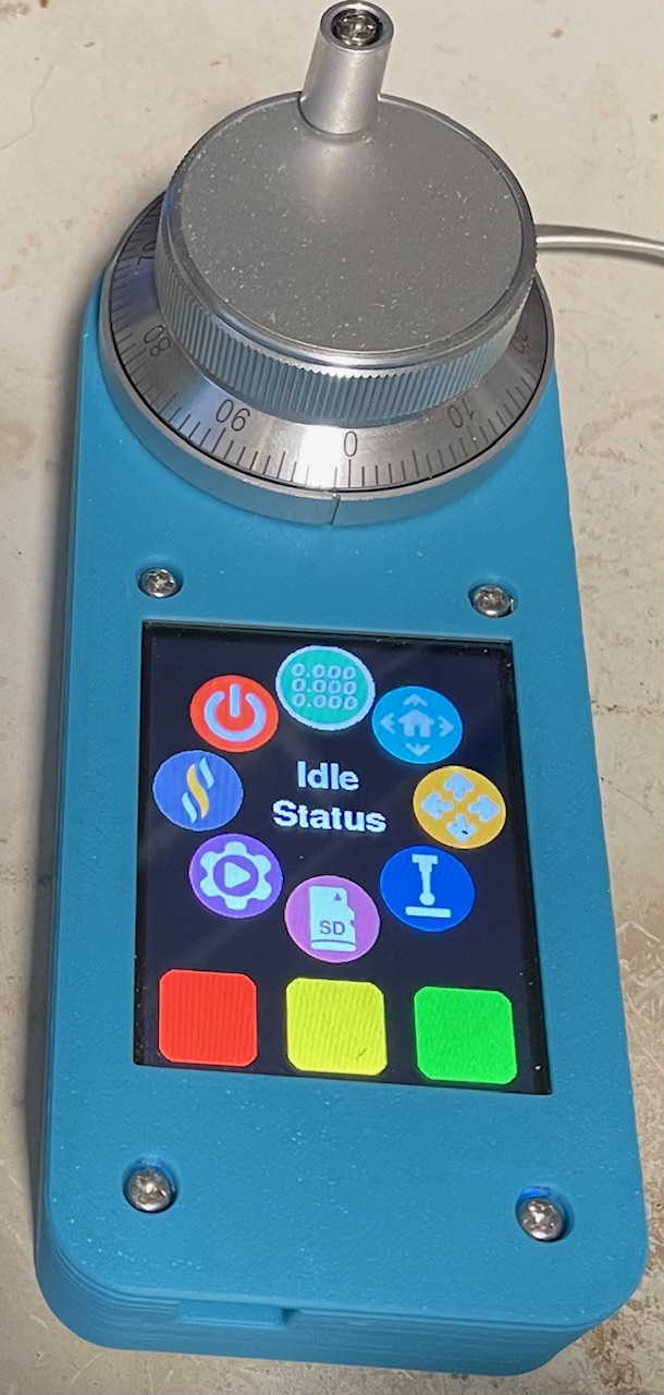
This is a pendant using a 2432S028 "Cheap Yellow Display" (with built-in ESP32) and a CNC Handwheel encoder. It has the same capabilities and the same user interface as the M5 Dial Pendant. A second firmware designed specifically for CYD Equipped Pendants with Physical Buttons is also available - see the Installing Firmware section for more info.
Compared to the M5 Dial Pendant, the CYD Dial Pendant
- Costs about the same
- Has a metal dial with better "action" and detents than the M5's plastic dial
- Has on-screen touch buttons instead of the M5's physical switches.
- Is physically larger; the M5 version can be made quite compact
- Uses most of the same code
Refer to the M5 Dial Pendant wiki page for user interface documentation.
¶ Info & Sourcing
¶ Material Sourcing
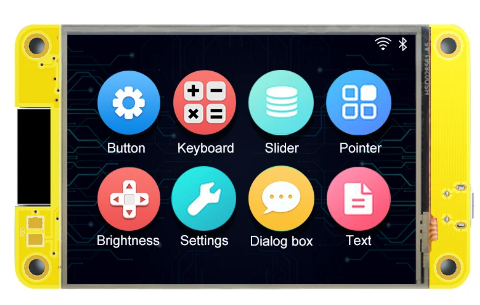
¶ Cheap Yellow Display
The supported part numbers for the display/ESP32 are 2432S028 (resistive touch) and JC2432W328C (capacitive touch). There are many listings for the resistive version on AliExpress, Amazon, EBay, Banggood, etc. The typical price is $10 from AliExpress and $20+ from Amazon or EBay.
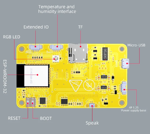
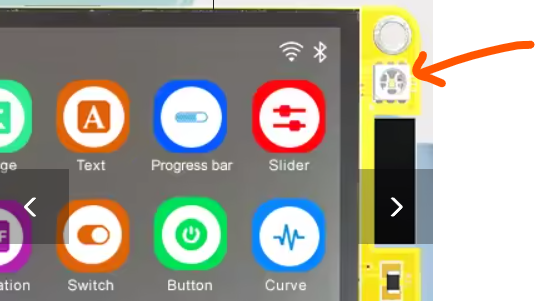
The capacitive version is somewhat less common; search AliExpress for "JC2432W328C". Guition also makes a resistive model JC2432W328R; this code does not support that one. The Guition models can be identified by the presence of an RGB LED on the front side as shown below; the other ones have the RGB LED on the back. The capacitive version has an extra IO connector on the back that affects the wiring.
If you can source it, the capacitive version is preferable because the capacitive touch is more responsive to finger touch than the resistive touch. Resistive touch works with fingers but you need to press harder.
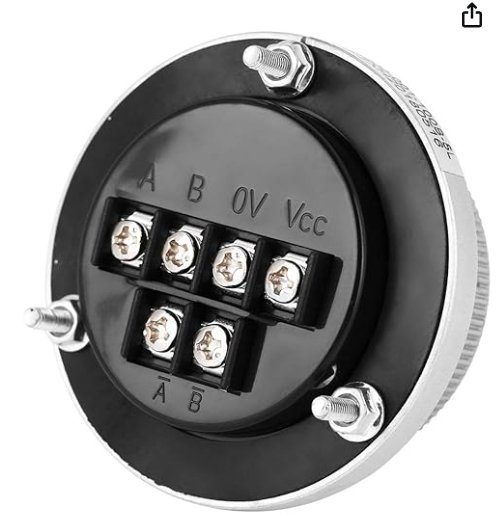
¶ CNC Handwheel Encoder
Search for "CNC Handwheel Encoder". You want a 60mm, 100PPR, 5V unit. Either the 4-terminal or 6-terminal version will work. They cost about $7 on AliExpress and about $18 on Amazon. You can also get them in black instead of silver.

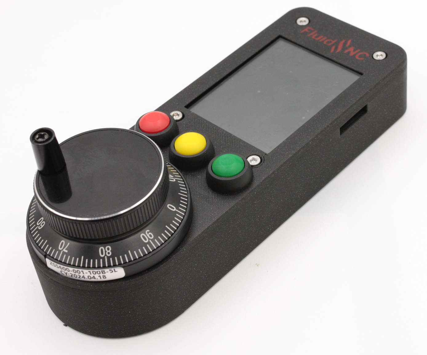
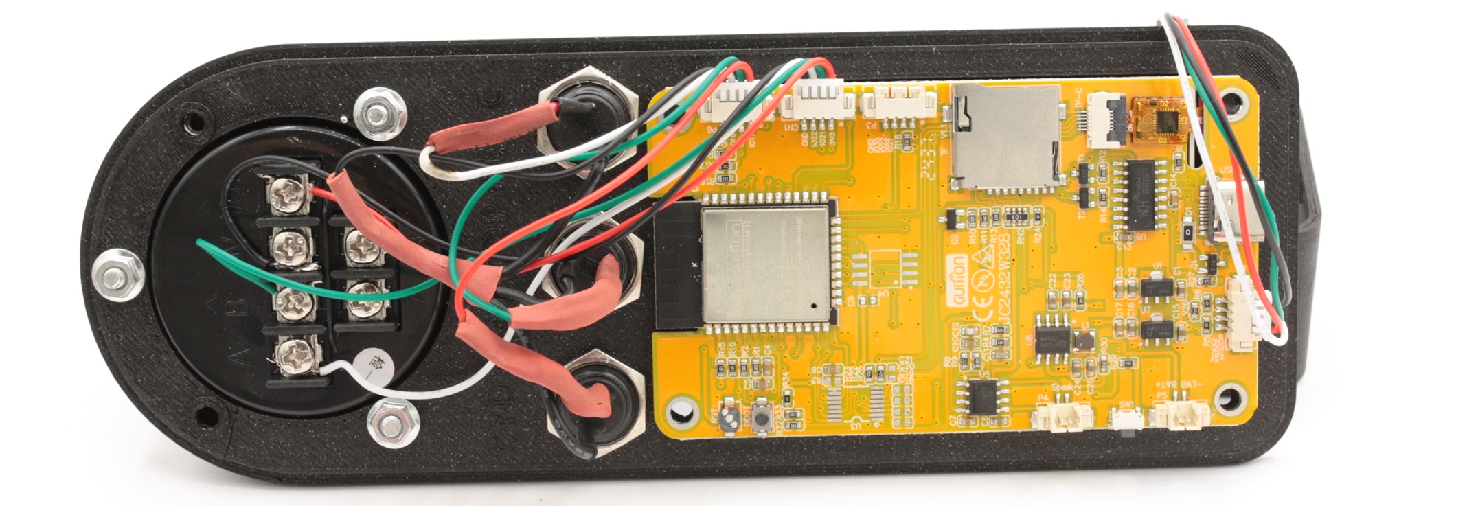
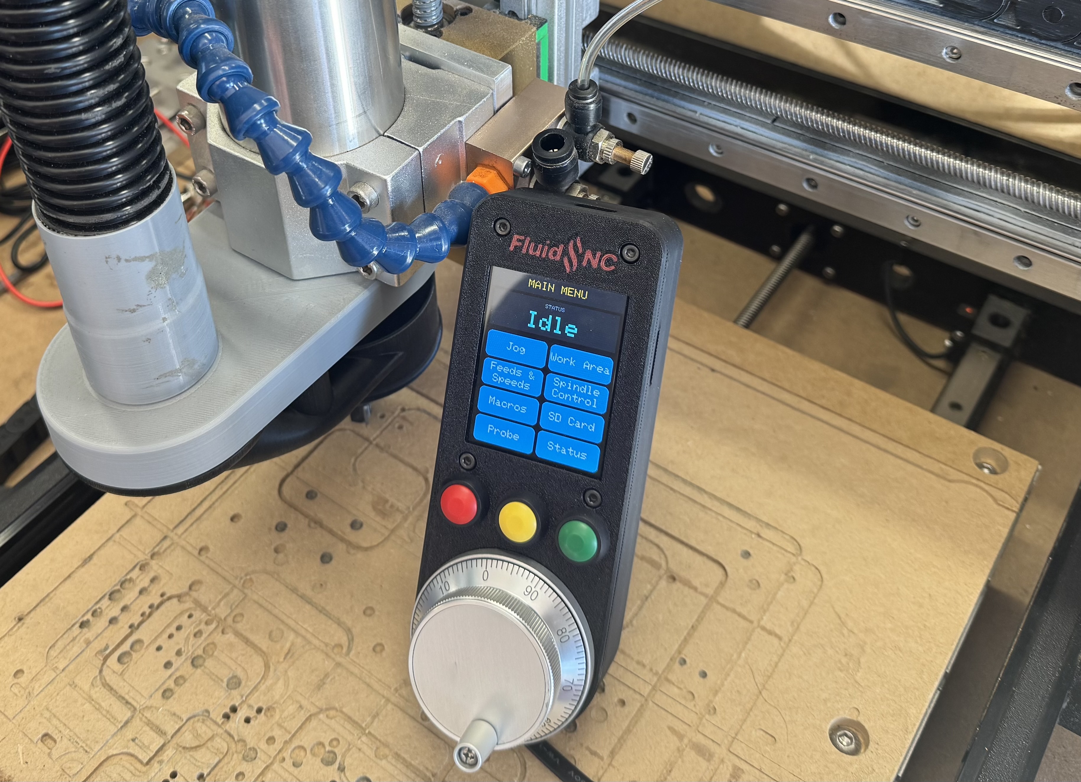
Example of a pendant with CNC Handwheel encoder and buttons:
¶ Alternative Encoder
You could also use a small rotary encoder like these
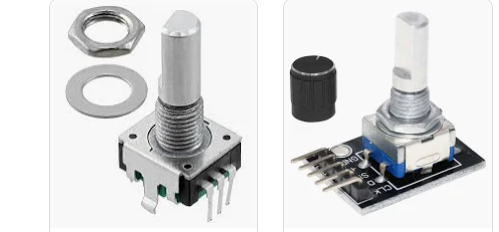
The CNC handwheel has a better feel, but is more expensive and larger. The small rotaries typically have an extra switch that activates when you press the knob down. That switch could be used for other purposes.
Example of a pendant with a small rotary knob and buttons:
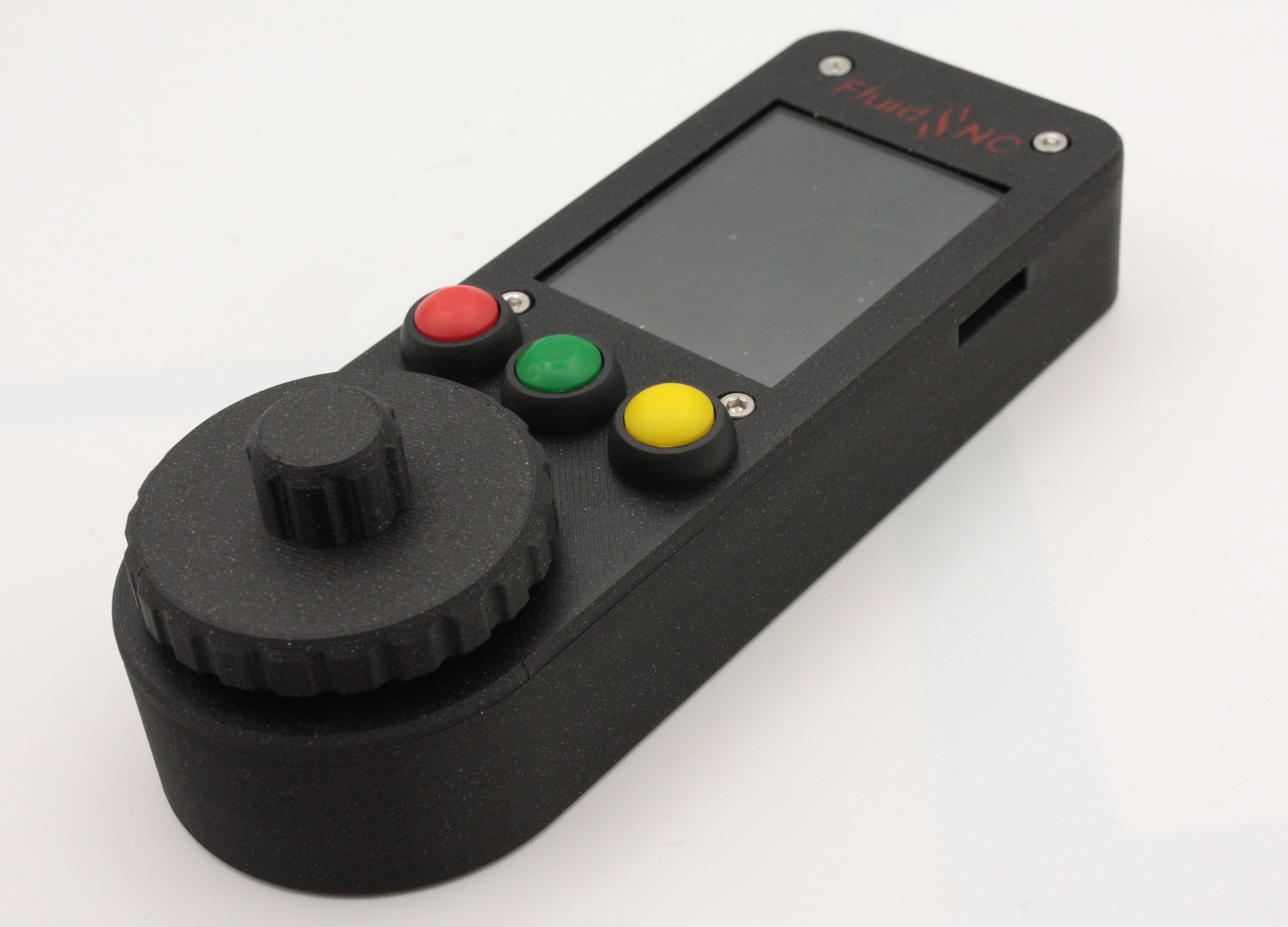
The previous case was made using the following rotary knob: amazon.
The 3D printed part that goes on the knob is available here: CYD_Dial_JC2432W328C_rotary_knob.stl .
¶ Physical Buttons
To utilise physical buttons, you will need momentary push buttons, nominally 12mm diameter. The coloured buttons, shown in the case above, can be found on Amazon by searching for “12mm Round Push Button Momentary Switch”. Other sizes could be used but you would have to modify the case.
¶ Connectors for CYD ports
The CYD board has some 4-pin IO ports. The mating connectors are JST-PB 1.25mm 4-pin, also known as PicoBlade. You need 3 such connectors for the version with physical buttons, or only 2 without buttons.
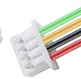
You can buy them with pigtails already attached, and you can also get them with Dupont connectors on the other end. When you buy the Cheap Yellow Display, it might come with one such connector with Duponts on the other end. Even so, you need a total of 3 or 4 such connectors, so you will have to buy more.
AliExpress
¶ RJ11 / RJ12 Breakout
A nice way to connect back to the FluidNC controller is with a 6-pin RJ12 data cable. That is directly supported by some newer interface boards at the FluidNC side. The 3D printed case is designed to accept this connector.
This breakout board is very convenient.
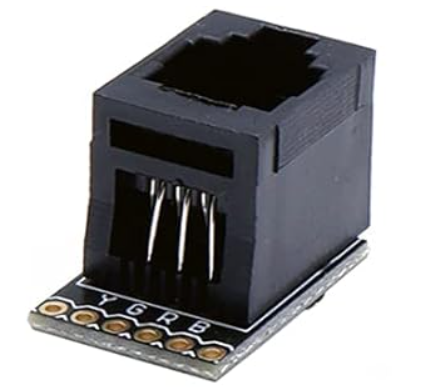
This breakout comes with the socket and the breakout board separate, so you will have to solder the socket to the board. It does not come with Dupont pins so you might want to purchase them separately. If you solder Dupont pins into the breakout you can make the connection to the CYD board with the Dupont females on the JST cables recommended above. Or you could solder pigtails from the JST connectors directly to the breakout.
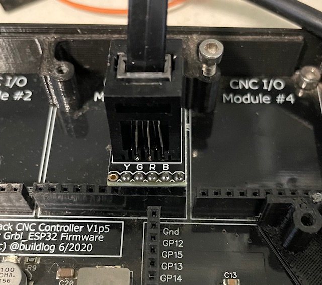
You can use this breakout on both ends, as the pinout is designed to plug directly into a 6-pack module socket.
Note that pin 6 is not populated in this picture, since neither pin 2 nor pin 6 is used for this wiring scheme. You can populate them or omit them, at your option.
¶ Pendant Interface
The Display / Pendant Interface Module is a great option for those with the 6x CNC Controller or 6 Pack Universal Controller - it provides a nicely integrated socket at the controller end of the chain, and is mechanically supported via a standoff. It is fully pin compatible with the RJ12 breakout board shown above.
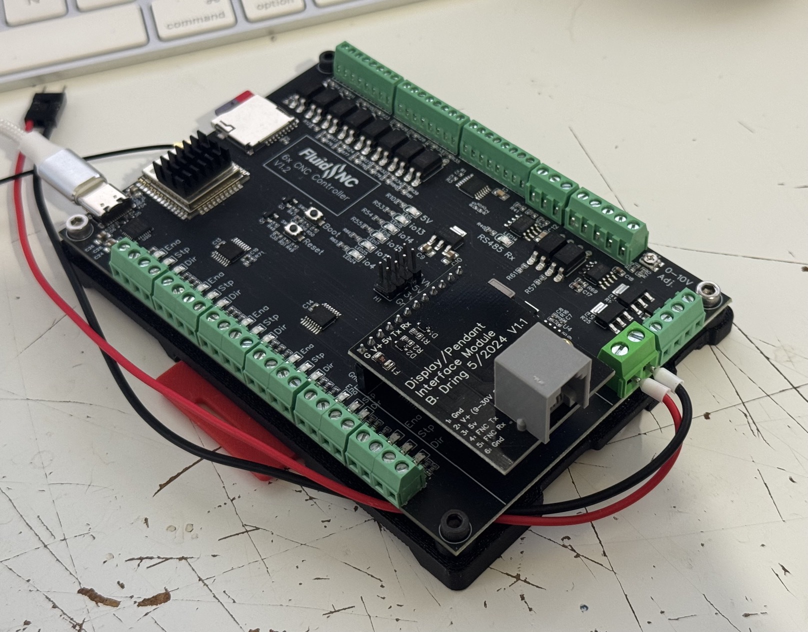
NOTE: The “FluidDial RJ12 Wiring Kit” is not electrically compatible with the CYD Dial Pendant, and physically doesn't fit inside the published pendant bodies - this kit is designed specifically for the M5 Fluid Dial Pendant.
¶ Alternatives
You could also use an RJ45 socket and use only the middle 6 pins, but you would have to modify the case. If you get an RJ45 breakout with screw terminals, you could avoid any soldering. Or you could hardwire the cable.
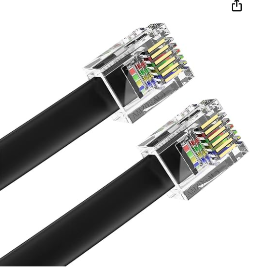
¶ Cable to FluidNC (6 conductor RJ12 straight-wired data cable)
Be sure to get straight wired, not crossover. The colors should match up in the orientation shown. It is highly recommended to use an ADSL/VDSL rated cable - cheaper cables can have signal integrity and connectivity issues.
¶ 3D files for case
¶ 2432S028 (resistive touch)
Fusion 360 Design for the CYD case Use this is you want to remix it.
¶ JC2432W328C (capacitive touch)
The design of the case is modifiable according to your use case.
Download the top and bottom 3mf files.
If you prefer, I have exported the different possibilities (STL files) to Printables.
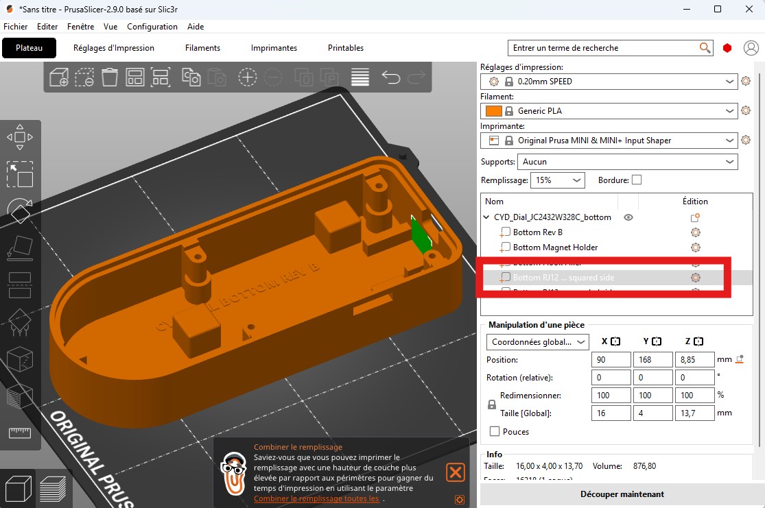
If you don't want to use an RJ12 port, you can print the part as is. If you want an RJ12 port on the flat side, delete the "Bottom RJ12 ... squared side" object. If you prefer to have the RJ12 port on the rounded side, delete "Bottom RJ12 ... rounded side".
You can also have hooks for attachments by deleting "Bottom Hook Filler"
Magnets can be used to attach the pendant to the machine. If this is your case, you must add a pause to the print at a height of 12mm. The maximum size of the magnets is 8x8x8mm.
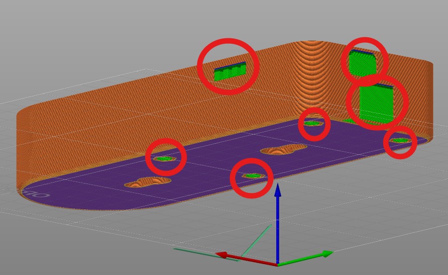
Add supports for USB port, SD card, RJ12 port and nuts:
It is possible to print the upper part with the logo in color. (There are two objects in the STEP file).
¶ Screws
The case is held together with four M3x12mm self-tapping screws that go through the mounting holes on the CYD board. The bottom of the case has alignment ridges to hold the CYD board in place while attaching the top with the screws. There is some leeway as to the screw length - anything between 8 and 16 mm will work, but the longer the screw, the harder it will be to screw in.
For the JC2432W328C version (capacitive touch): Instead of self-drilling screws, it is possible to use M3x20 screws or longer. A location for the nut is available on the underside of the case.
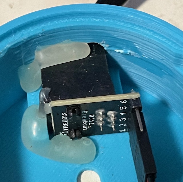
¶ RJ11/RJ12 Connector Mounting
The specified connector slides into guides in the bottom of the case. Then you can glue it to the case to hold it in place. I used hot glue.
¶ Wiring
¶ Note:
The TX and RX labels on the CYD board are swapped from what the FluidDial firmware uses. Check the diagrams below for the correct wiring.
¶ Capacitive CYD Wiring
The capacitive version has three IO connectors along the top, with pin assignments:
| Connector | Pin1 | Pin2 | Pin3 | Pin4 | Notes |
|---|---|---|---|---|---|
| P6 | GND | IO16 (GREEN_BUTTON) | IO4 (RED_BUTTON) | IO17 (YELLOW_BUTTON) | These pins are also connected to the RGB LED |
| CN1 | GND | IO22 (ENC_A) | IO21 (ENC_B) | 3.3V | |
| P3 | GND | IO35 | IO22 | IO21 |
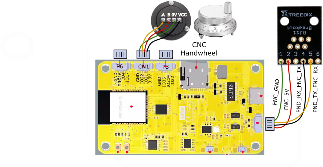
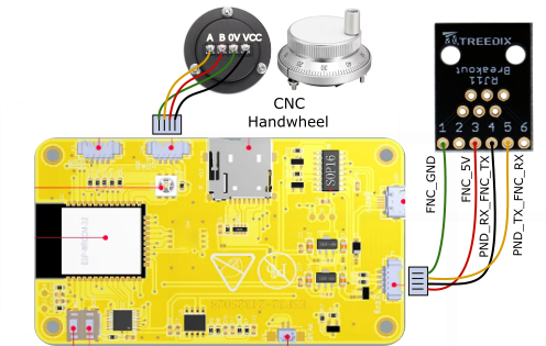
¶ Capacitive CYD Wiring with Handwheel
This is the basic wiring for the capacitive CYD, with handwheel, without physical buttons. To upload new firmware with this wiring, you must unplug the FluidNC serial connection and plug in the USB port.
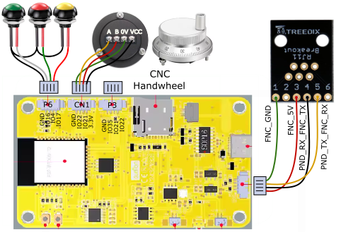
¶ Capacitive CYD Wiring with Handwheel and Buttons
As an extension to the base wiring, the RGB LED GPIOs that appear on the P6 connector can be used for button switches. The firmware will use them if they are present. To upload new firmware with this wiring, you must unplug the FluidNC serial connection and plug in the USB port.
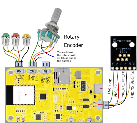
¶ Using a Rotary Encoder Instead of a Handwheel
A small rotary encoder can be substituted for the handwheel. The wiring is almost the same as for the handwheel, but the encoder does not require a VCC supply so the 3.3V wire from CN1 is a no-connect. The image below shows the rotary encoder with button switches, but you could omit the switches. If your rotary encoder has a switch that is activated by pushing down on the knob, that switch could be used instead of or in addition to (via a parallel connection with) one of the button switches.
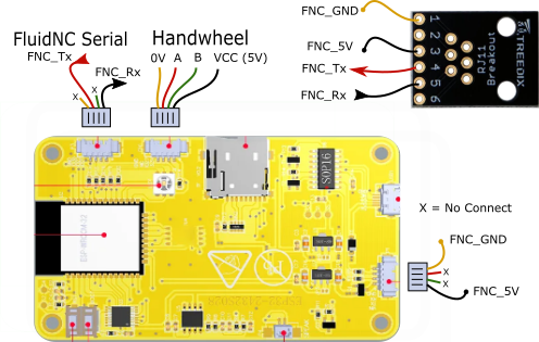
¶ Resistive CYD Wiring
The resistive CYD has two IO connectors along the top, with pin assignments as follows. Unlike the capacitive CYD, the resistive version does not have a connector that brings out the pins that connect to the RGB LED, which can be used for physical buttons on the capacitive version. Some users have reported using physical buttons with the resistive version by soldering wires to the RGB LED pins. That is unsupported, but might work if you have the skill to do it.
| Connector | Pin1 | Pin2 | Pin3 | Pin4 | Notes |
|---|---|---|---|---|---|
| P3 | GND | IO35 | IO22 | IO21 | IO21 also controls the backlight |
| CN1 | GND | IO22 (ENC_A) | IO27 (ENC_B) | 3.3V |
¶ UI Lockout Feature
The wiring can further be extended to include a “lockout” switch that, when closed, will disable all user interaction, including the touchscreen, rotary encoder/handwheel, and the buttons. The switch must be connected between 3.3V and the R21 photoresistor on the top side of the board above the display. Solder a wire to that photoresistor on the side nearest the middle of the board (the side near the ESP32 antenna) and connect it to a normally-open switch. Connect the other side of the switch to a 3.3V point such as CN1 pin 4 (the pin that connects to the handwheel VCC). Support for the lockout feature is present in the release builds; if you do not want to use it, do not connect a switch to the board.
Development of this feature was funded by a donation from Discord user Martin_LB .
¶ Legacy Wirings
These wiring plans are no longer recommended and are not supported by released firmware builds. To use them you must compile the firmware yourself. The information is provided for historical purposes.
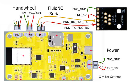
¶ Resistive CYD Legacy Wiring
This wiring requires three 4-pin connectors and allows you to use the USB port for debugging while connecting a separate UART channel to FluidNC. The platformio compile env is env:cyd_resistive. The pin assignments are:
| Connector | Pin1 | Pin2 | Pin3 | Pin4 | Notes |
|---|---|---|---|---|---|
| P3 | GND | IO35 (PND_RX_FNC_TX) | IO22 | IO21 (PND_TX_FNC_RX) | IO21 also controls the backlight |
| CN1 | GND | IO22 (ENC_A) | IO27 (ENC_B) | 3.3V |
¶ Capacitive CYD Legacy Wiring for USB Debugging
This wiring requires three 4-pin connectors and allows you to use the USB port for debugging while connecting a separate UART channel to FluidNC. There is no preset platformio compile env for this wiring.
¶ Installing Firmware
FluidNC Web Installer can install FluidDial to supported (non-legacy) CYD Dial configurations.
- Unplug the connection between the CYD and the FluidNC controller
- Connect the CYD USB port to your computer
- Go to FluidNC Web Installer
- Select the FluidDial option from the main menu
- Use the Connect button to establish a USB connection between your computer and the CYD
- Choose the FluidDial for CYD installation type
- After the installation finishes, you can disconnect the USB cable and reconnect the FluidNC cable.
The first time that the CYD starts, it will ask you to touch the screen to determine which touch screen option is present on your hardware. It cycles between screens that say “Resistive .. Tap the Screen” and “Capacitive .. Tap the Screen”. When the proper option appears, touch the screen. When the CYD recognizes a touch event, the correct driver will be chosen, remembered, and used for subsequent operations. It is only necessary to do this once after each reinstall of the firmware.
You do not have to be careful to tap the screen at exactly the right time. When the wrong driver is installed, the device will not see touches, so you can just tap tap tap tap until it works.
If you have problems with FluidNC Web Installer, there are some alternative methods you can try. The precompiled binary images can be downloaded from this repository . They can be installed with any “esptool” ESP32 firmware download program The merged-flash.bin image should be downloaded to FLASH at address 0x0000. One such download program is this web installer; there are many others.
¶ Alternate Firmware
FluidDial-CYD is a custom firmware for CYD-equipped FluidDial CNC pendants and supports Wired conectivity or WiFi + Li-On Battery. The UI has been rebuilt from the ground up for devices with 3 physical buttons and a jog dial. Includes onboard support for Z Surface Probes, XYZ Probes and 3D Touch probes. Supports Z Surface, XYZ Corner, Bore, and Boss Probing. The Web Installer for FluidDial-CYD is HERE.
¶ Compiling Firmware
If a released version does not meet your needs, either because you want additional features or because your hardware configuration is not supported, you can compile the firmware yourself.
Please do not ask for help with unsupported setups unless you are a project sponsor . We barely have time to help people with supported hardware; assisting people with one-off customizations requires time that we would rather use in developing technology applicable to many people.
- Install VSCode and its PlatformIO extension
- Git-clone the FluidDial Source code (main branch)
- Use Visual Studio Code with PlatformIO to compile and upload the code.
- Connect your display to the computer via a USB cable.
Be sure to do all the tasks below.
¶ Compile and upload the firmware
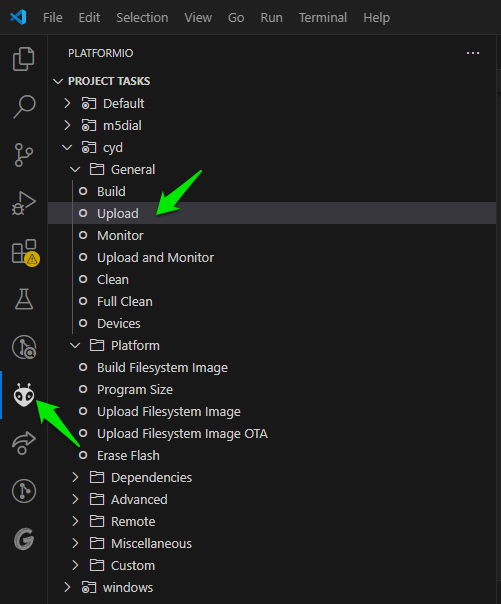
- Click on the Platformio icon on the left column
- Click on Upload under PROJECT TASKS/cyd/Upload
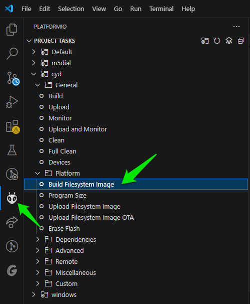
¶ Build the filesystem image
This creates the file system with the icons and images.
- Click on the Platformio icon on the left column
- Click on Build Filesystem Image under PROJECT TASKS/cyd/Platform
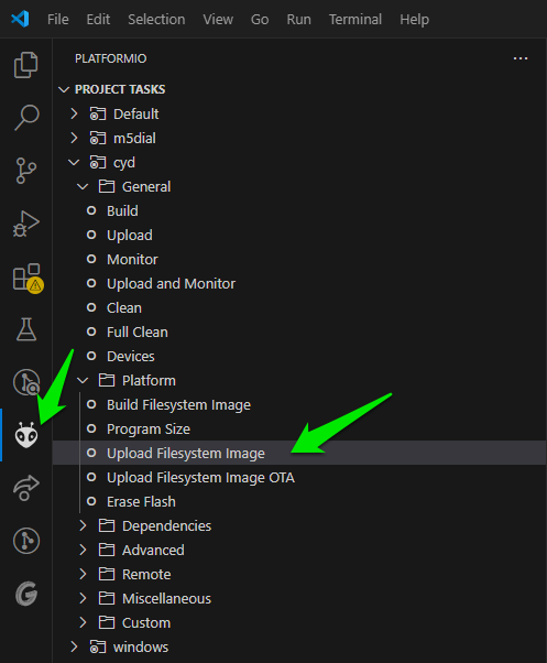
¶ Upload the filesystem image
- Click on the Platformio icon on the left column
- Click on Upload Filesystem Image under PROJECT TASKS/cyd/Platform
¶ FluidNC Config Example
See the config example for FluidDial
You can use any 2 pins on the ESP32 that are UART capable (most are)
The default baud rate is 1000000. It can be changed in platformio.ini in this statement
DFNC_BAUD=1000000The config file Tx and Rx are with respect to the FluidNC. Be sure to connect the FluidNC Tx to the pendant's Rx and the FluidNC Rx to the pendant's Tx.
FluidNC configuration example for "6x CNC Controller" with "Simple Pendant Module":
uart1:
 txd_pin: gpio.25
 rxd_pin: gpio.27
 rts_pin: NO_PIN
 cts_pin: NO_PIN
 baud: 1000000
 mode: 8N1

uart_channel1:
 report_interval_ms: 75
uart_num: 1¶ Usage
See the usage instructions for FluidDial
Use the on-screen red, green, and yellow touch buttons in place of FluidDial's physical switches and its dial switch.
¶ Orientation
To change the display orientation so you can use the CYC Dial Pendant with the handwheel in different positions relative to the screen, go to the About screen and rotate the handwheel. The orientation will change with each click of the wheel. The orientation will be saved so the pendant will start in the chosen orientation. The default orientation has the handwheel on top and the red/green/yellow buttons on the bottom.
Warning: this feature no longer works (See issue #17). You need to modify the code to change the orientation.
¶ CYD Pin List
The spreadsheet shows connections for the common resistive CYDs that follow the Sunton design, and both resisitive and capacitive touchscreen versions from Guition. TF signals are for the SD card. TFT signals are for the display. RTP signals are for the resistive touchpad which is connected via an SPI bus. CTP signals are for the capacitive touchpad which is connected via an I2C bus.
|
Pin |
ESP32 usage |
Sunton Resistive |
Guition Resistive |
Guition Capacitive |
|---|---|---|---|---|
| IO0 | BOOT | |||
| IO1 | U0TXD | P1-3 | P1-3 | P1-3 |
| IO2 | TFT_RS | TFT_RS | TFT_RS | |
| IO3 | U0RXD | P1-2 | P1-2 | P1-2 |
| IO4 | LED_RED | LED1_2 |
LED1_2 P6-3 |
|
| IO5 | VSPI CS0 | TF_CS | TF_CS | TF_CS |
| IO6 | SCK | |||
| IO7 | SDO | |||
| IO8 | SDI | |||
| IO9 | SHD/SD2 | |||
| IO10 | SWP/SD3 | |||
| IO11 | CSC/CMD | |||
| IO12 | HSPI MISO | TFT_SDO | TFT_SDO RTP_OUT | TFT_SDO |
| IO13 | HSPI MOSI | TFT_SDI | TFT_SDI RTP_DIN | TFT_SDI |
| IO14 | HSPI CLK | TFT_SCK | TFT_SCK RTP_CLK | TFT_SCK |
| IO15 | HSPI CS0 | TFT_CS | TFT_CS | TFT_CS |
| IO16 | U2TXD | LED_GREEN | LED1_3 |
LED1_3 P6-2 |
| IO17 | U2RXD | LED_BLUE | LED1_1 |
LED1_1 P6--4 |
| IO18 | VSPI CLK | TF_CLK | TF_CLK | TF_CLK |
| IO19 | VSPI MISO | TF_SDO | TF_SDO | TF_SDO |
| IO21 | I2C SDA |
BL_CTRL P3-4 |
CN1-3 | CN1-3 |
| IO22 | I2C SCL |
CN1-2 P3-3 |
CN1-2 P3-3 |
CN1-2 P3-3 |
| IO23 | VSPI MOSI | TF_SDI | TF_SDI | TF_SDI |
| IO25 | RTP_DCLK | CTP_RST | ||
| IO26 | SPK | SPK | SPK | |
| IO27 | CN1-3 | BL_CTRL | BL_CTRL | |
| IO32 | RTP_DIN | CTP_SCL | ||
| IO33 | RTP_CS | RTP_CS | CTP_SDA | |
| IO34 | INPUT ONLY | R21(photoresistor) | R21(photoresistor) | R21(photoresistor) |
| IO35 | INPUT ONLY | P3-2 | P3-2 | P3-2 |
| IO36 | INPUT ONLY | RTP_IRQ | RTP_IRQ | |
| IO39 | INPUT ONLY | RTP_DOUT |
¶ Donations
Developing, testing, documenting, and supporting the various FluidDial pendants required hundreds of hours of work and the purchase of many hardware items. If you build one, please consider sponsoring the FluidNC project.