¶ Overview
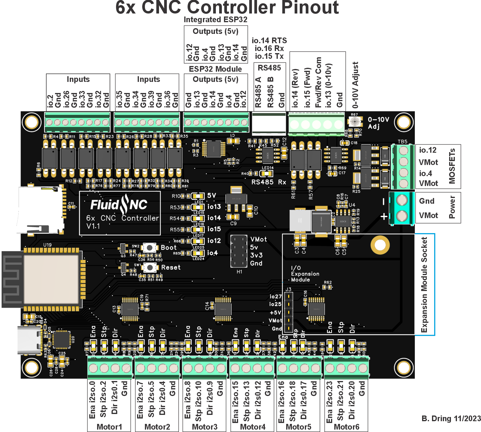
There are (2) versions of this controller. One uses a plug in ESP32 and one has one built into the controller. They have indentical pinouts and roughly the same placement of all the connectors. Unless otherwise noted, this page covers both versions.
¶ Where to buy it.
¶ Features
- (6) Motor connectors for external stepper drivers (5v signals). Each motor has separate step, direction and enable signals. LEDs are on each signal to help with setup.
- (8) Inputs for switches (limits, probes, control)
- Spindles (many types supported). Some multi-spindle arrangements are possible like RS485 & laser on the same machine.
- RS485 VFD Spindles
- 0-10V controlled spindles with additional forward and reverse direction signals
- PWM Speed controllers with optional separate enable signals
- Relay (on/off) controlled spindles.
- BESC (Brushless Motor) based spindles
- Lasers with PWM and enable
- (2) 3A MOSFETs to drive relays, solenoids and valves.
- Unused spindle 5V outputs can be used for any output function (coolant, etc)
- Micro SD card socket for local storage of gcode files
- Module socket for GPIO extenders and Pendant interfaces.
¶ Versions
Currently, all of the versions use the same I/O. Config files are compatible between versions.
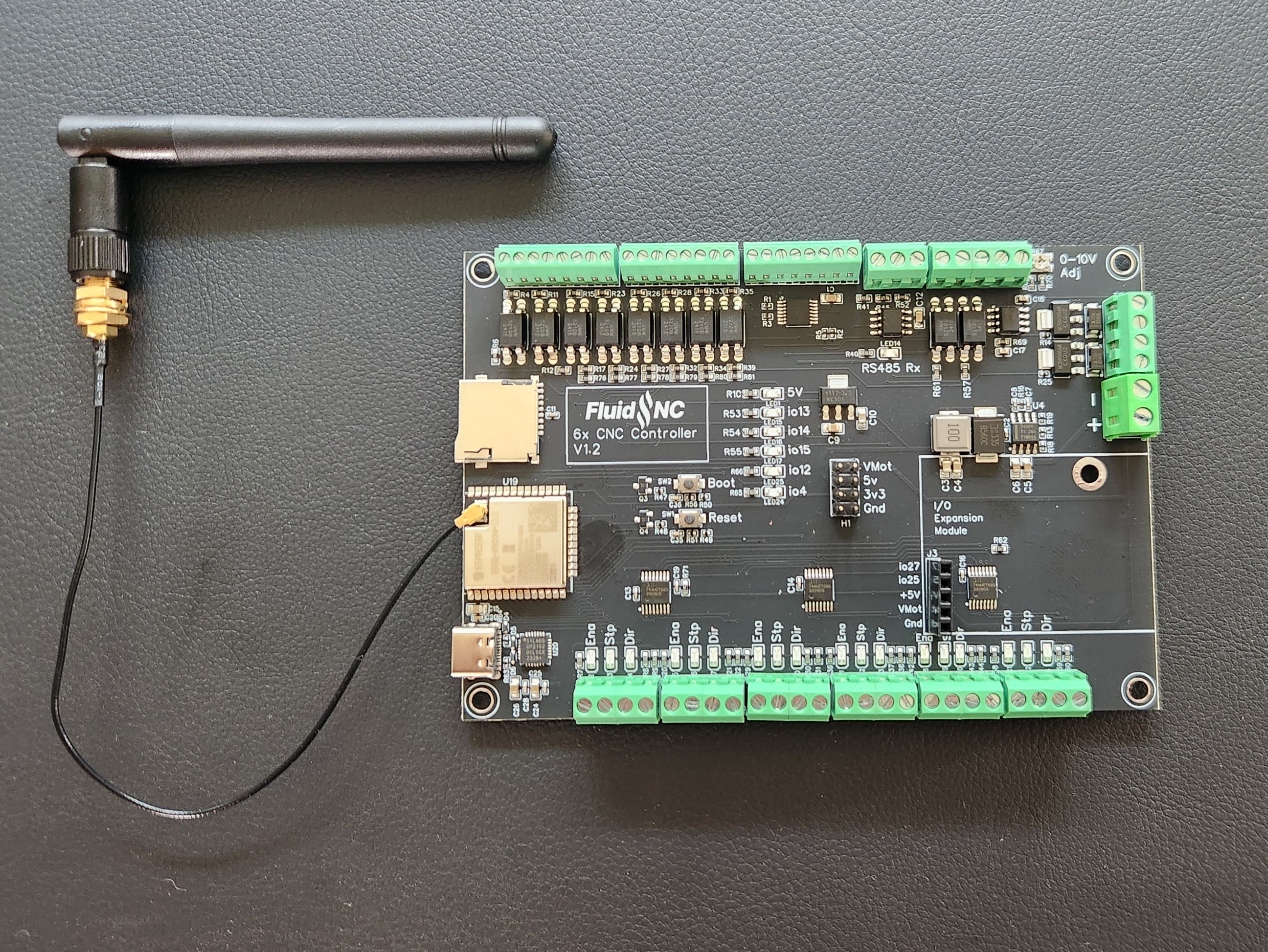
- V1.2 This version changed from the PCB antenna ESP32 to the PCB connector version. This did not change the PCB layout because the 2 footprints are compatible.
¶ Getting Started
The controller ships with a version of FluidNC that was current when the controller was built. You upgrade the firmware using the web installer.
- Do not install your config file yet.
- Do not connect any external devices yet.
- Do not connect the USB yet. It will not work yet anyway.
- Connect the antenna. You should only operate when the antenna is connected. A missing antenna can cause the device to overheat.
- Connect main power. Be sure the polarity is correct before you turn on the power.
- Turn on the main power and confirm that the 5v LED is lit.
- Connect a USB-C cable between your computer and the controller. Check to see that your computer has added a serial port. See below if you have a problem.
- Go to the web installer. Connect to your controller and do an upgrade.
- You may want to connect to your wifi at this time.
- Now create and load a config file for your machine.
- Power down and connect all your devices. It might be helpful to connect just a few at a time and test as you go.
¶ USB C connector
The USB chip is a Silicon Labs CP2102 USB to serial chip. Many operating systems ship with the drivers installed already. It's recommended to get the latest driver here if you run into issues connecting.
It ships with a default config file that is primarily used for factory testing and will probably not run your machine. You will need to create a config file for your machine and upload it.
¶ Asking For Help
Before asking for help, please search all areas of this wiki. Your questions have probably been asked before and long detailed answers with photos, drawings and schematics are on this wiki.
See this help page if you still have problems.
Please ask all other questions via our discord server.
¶ Built in ESP32
This uses a USB-C connector. The main power must be on to to power the USB chip. You will not get a connection to your computer if the main power is not on.
¶ Power Supply
The controller must be powered via a 12-30VDC power supply. This primary voltage is called VMot on the schematic and in the documentation. It should be able to supply a minimum of 2A. If you are attaching external devices to any of the VMot connections, you should add those currents to the power supply minimum.
There is a header in the middle of the controller for access to all controller voltages. These are for low current only. You should not pull more than 1A from any of these connections.
VMot is also accessible on the MOSFET terminals. You can pull up to 3A on each of these pins.
You should not power a spindle or laser from this controller. Use separate wiring from your power supply from this.
You cannot power the controller with USB alone. The USB will not connect.
Be very careful getting the voltage polarity correct. There is no reverse polariy protection, so you will destroy the controller and probably some connected items.
There is a central header that provides the user access to these voltages.
- 3.3V 100mA max total
- 5V 500mA max total
- VMot 1A per pin max.
¶ Programming
The controller is programmed with the current FluidNC revision at the time it was produced. It also has a very basic config file that is used for testing. There is a testing gcode file that blinks the LEDs and moves the motors. You should check for updates before using the controller. The version is shown in the startup messages. Send $ss to see them after again startup. The current FluidNC release is always listed here.
Apply power to the controller via the power terminal block. Check that the 5v LED in the middle of the PCB in lit. Connect a high quality USB C cable to the controller. Connect the other end to a PC (Windows, Mac or Linux).
Use the Chrome browser to connect to the FluidNC Web Installer page. Click the connect button. Select the COM port associated with controller. The USB device is a Silicon Labs CP2102. If you see several COM ports available, look for one with a description similar to that. Select it, so the web page connects to it.
Install the version with the highest number. Do not use any test releases unless instructed to do so to help with a support issue.
See the general installation page for more information and alternative methods.
¶ Motors
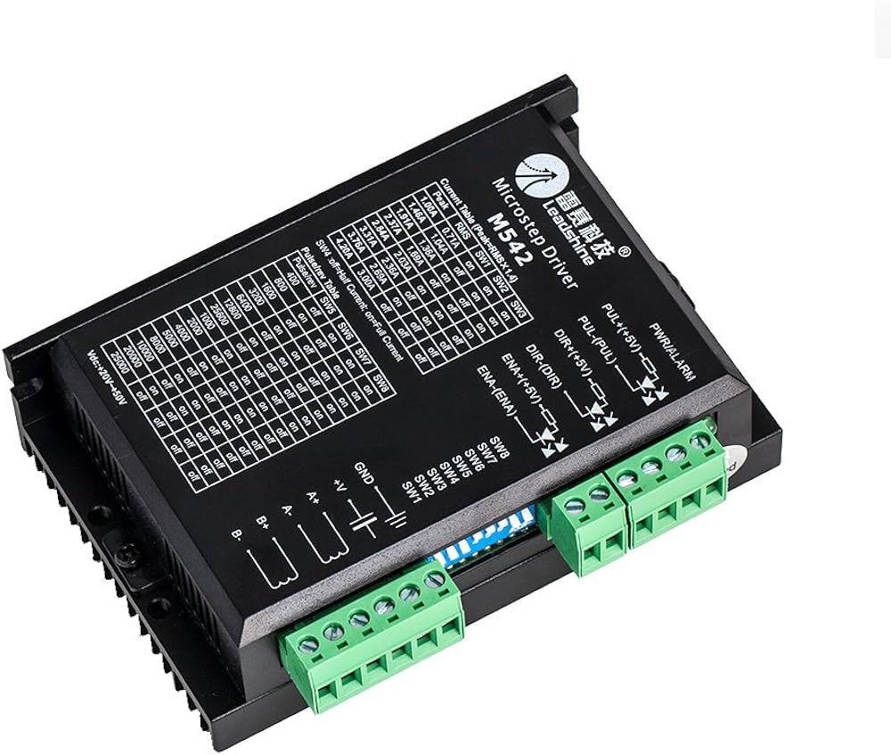
The controller is designed for external stepper driver modulesexternal_stepper_motor_drivers that accept 5V step, direction, and enable signals. They all use i2so pins, so you need to use I2S_STATIC or I2S_STREAM in the stepping section of your config file.
stepping:
  engine: I2S_static
  idle_ms: 255
  pulse_us: 4
  dir_delay_us: 4
  disable_delay_us: 0
  segments: 6
Any motor output can be used for any axis or motor number. They are labeled Motor1 through motor6, just for reference. Here are the pins for each motors.
# motor 1
      standard_stepper:
        step_pin: I2SO.2
        direction_pin: I2SO.1
        disable_pin: I2SO.0

# motor2
      standard_stepper:
        step_pin: I2SO.5
        direction_pin: I2SO.4
        disable_pin: I2SO.7

# motor3
      standard_stepper:
        step_pin: I2SO.10
        direction_pin: I2SO.9
        disable_pin: I2SO.8

# motor4
      standard_stepper:
        step_pin: I2SO.13
        direction_pin: I2SO.12
        disable_pin: I2SO.15

# motor 5
      standard_stepper:
        step_pin: I2SO.18
        direction_pin: I2SO.17
        disable_pin: I2SO.16

# motor 6
      standard_stepper:
        step_pin: I2SO.21
        direction_pin: I2SO.20
        disable_pin: I2SO.23
¶ Motor Wiring
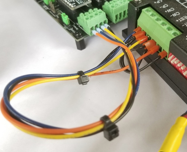
The best way to wiring the motor is to use a common ground. Wire the ground terminal of the controller to one of the (-) terminals of the stepper driver, then daisy chain it to the 2 other (-) terminals. See the black wire in the image above. Next, individually wire the step, dir, and enable terminals on the controller to the equivalent (+) terminals on the stepper drivers. If any fuction is reveresed, like enable or dir change the active state of the pin.
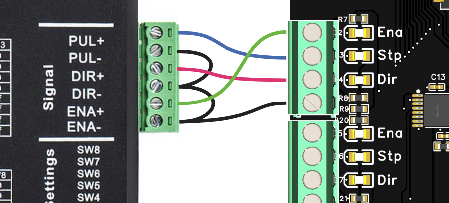
The Ena, Stp and Dir LEDs on the 6x Controller can help you verify the signals. The LEDs show the electrical state of the signal. If the signal is high (5v), the LED will be on. If it is low (gnd), the LED is off. Depending on whether your disable signal is active high or active low will determine if the LED is on or off when your motors lock. You should just look to see if it changes when you send $MD and $ME. The direction LED will be on for one direction and off for the other direction. The step LED will typically glow dimmer than the other LEDs with the brightness proportional to the speed. This is because the step signals are very short pulses. If you are inverting the active state of the step signal, the LED activity will also be inverted.
¶ Closed loop motors
Most closed loop motor drivers can be used. See this wiki page for more details.
¶ Inputs
All inputs activate by closing the circuit to ground. You can use N.O. and N.C switch as long as one position closes to ground.
You can use electronic switches like proximity or inductive switches as long as the output signal switches to ground (typically called NPN). If the switches require external power you need to connect that elsewhere on the controller or an external power supply that shares a common ground. In any state the switch should never put more than 5V on the terminal block. Often the NPN types will have an internal pullup resistor on the signal to the + voltage. This is usually about 10k. As long as it is 5k or higher, it should be safe to connect to the input.
All of the inputs have external pullup resistors except for gpio.2 and gpio.26. You should add the :pu attribute to those. gpio.2 is a strapping pin, so an external pullup cannot be used.
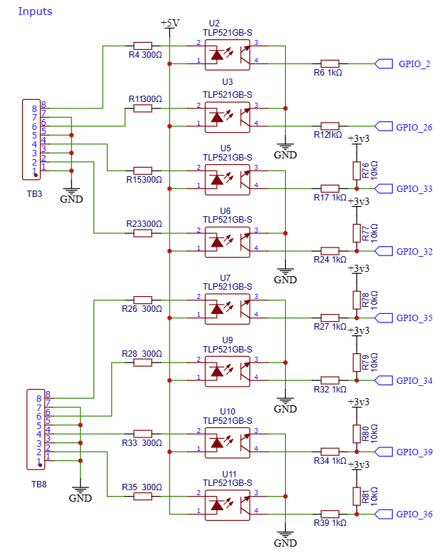
For normally open switches you need the *:low attribute on all inputs. Normally closed are active high. You can add the :high attribute, but it is not needed because that is default in FluidNC.
Example:
gpio.2:low:pu
gpio.36:low
gpio.39
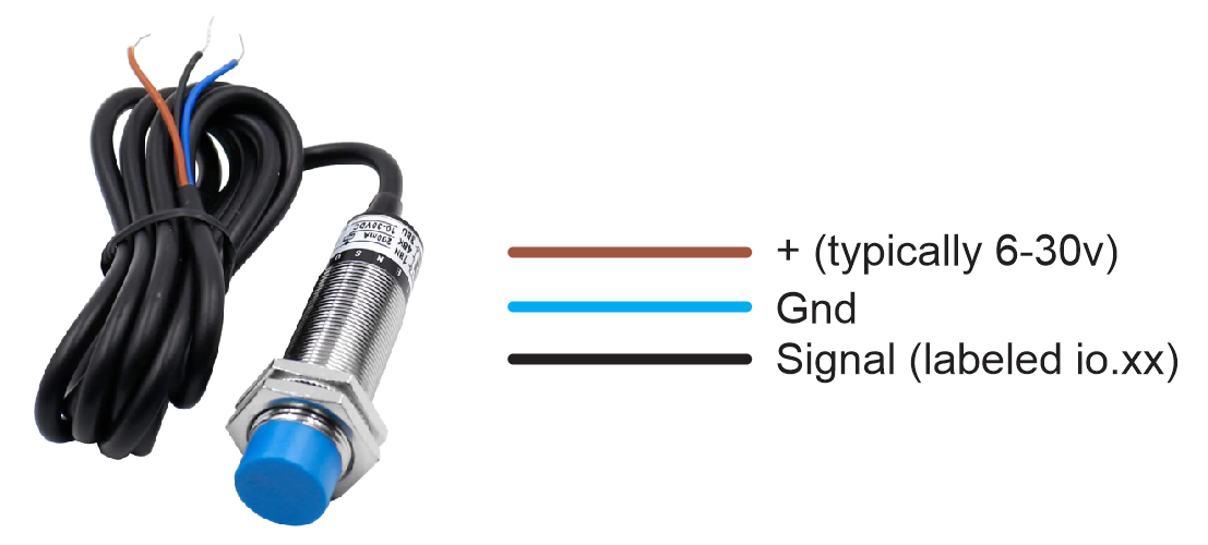
Example NPN proximity switch wiring.
6x switch inputs work by connecting the signal pin to ground. This means you must use an NPN type proximity switch. PNP types will connect the signal to the plus voltage, which will not activate the circuit and could damage the opto.
Connect the brown wire to a voltage compatible with the sensor (typically 6-30v). You can use the voltage header in the middle of the controller. Connect the blue wire to any ground. Connect the black wire to Inputs labeled io.xx.
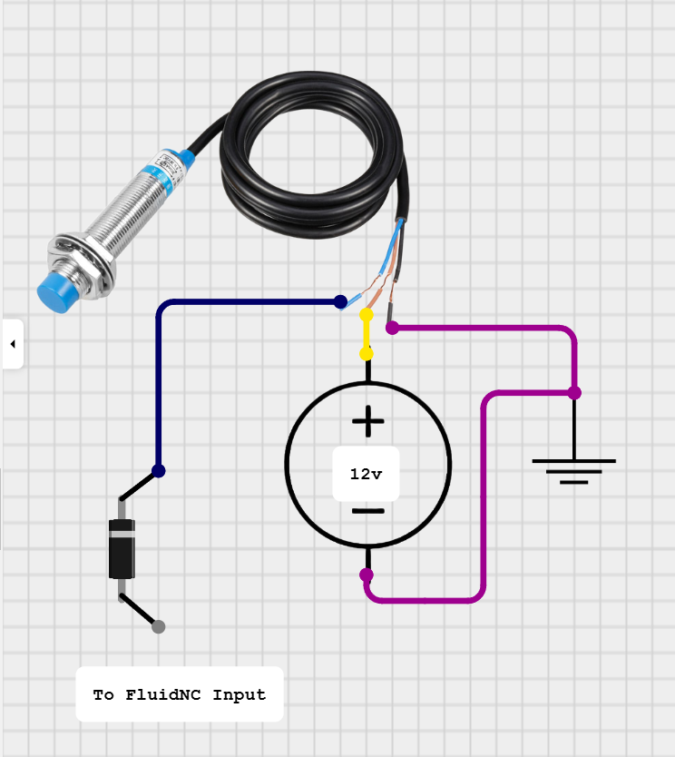
Warning: Some NPN switch circuits can have a pullup resistor to the positive voltage. If this voltage is more than a volt or 2 above the 5V on the other side of opto LED on the 6x controller input circuit, it can create a harmful reverse potential on the LED. You can use a meter to see signal voltage in the active and inactive states. You can use a diode to prevent and reverse voltage as shown below.
¶ Outputs
The controller has a lot more output connections than I/O pins. It does this by sharing I/O pins. For example, the MOSFET uses the same I/O as some of the 5V outputs. When you assign that I/O pin, you can either use the 5V output or the MOSFET. They are linked and active at the same time. You cannot use them for separate features. See the I/O map.
¶ 5V Outputs
A 74AHCT125 chip is used to convert the ESP32 3.3V to 5V. They are designed for about 8-10mA per channel. The absolute max is 25mA per channel and 50mA total for all 4 outputs.
¶ I2SO Outputs
The i2so pins are typically used for motor control, but you can use them for other digital (on/off) output functions. If for example you are not using a 6th motor, you could use any of the those pins, like mist_pin: i2so.23. See more on i2s0 pins here.
¶ Spindles
Many of the spindles share outputs with other features. Keep track of the I/O you are using to avoid conflicts.
¶ PWM
The PWM can be put on any of the 5V outputs.
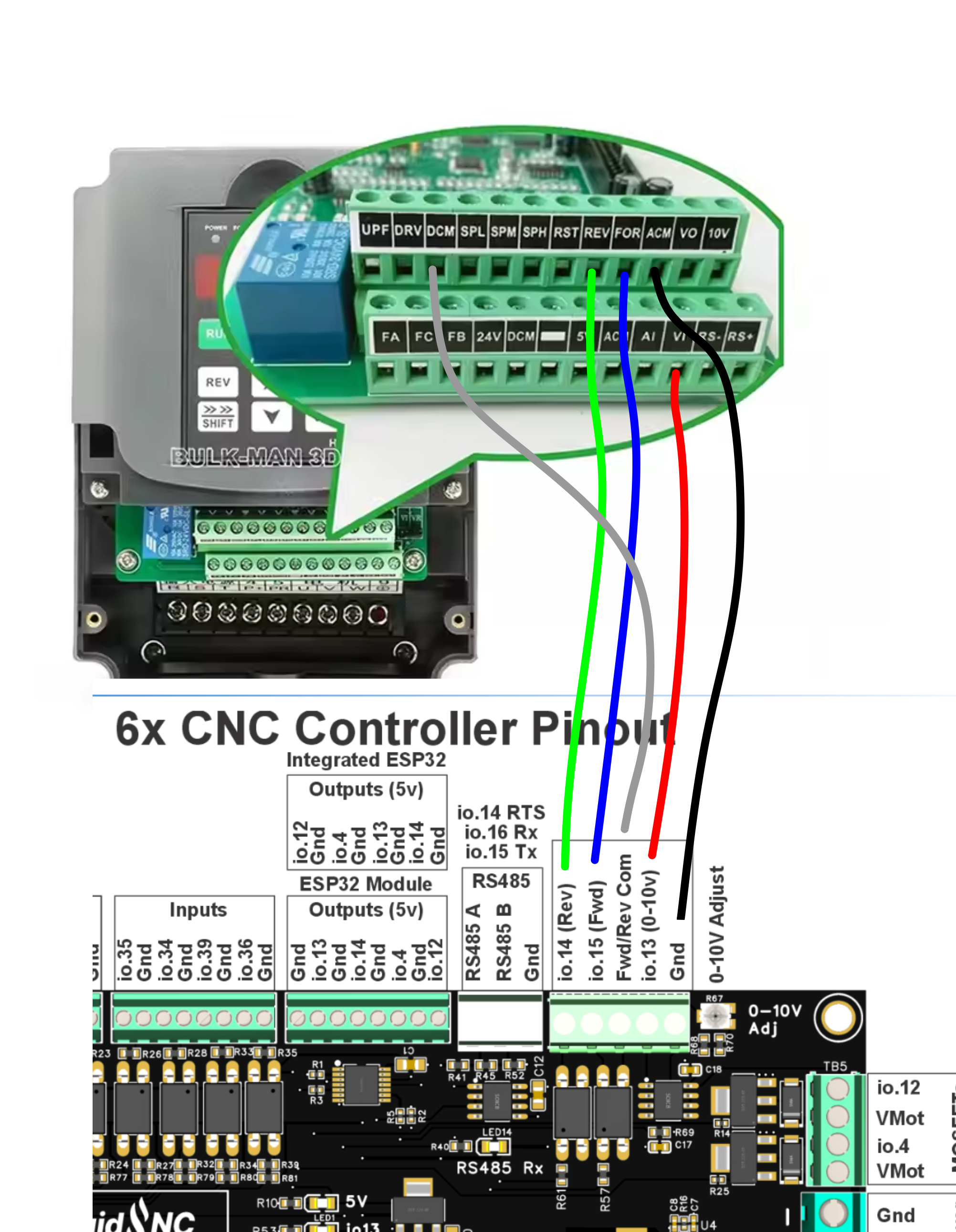
¶ 0-10V
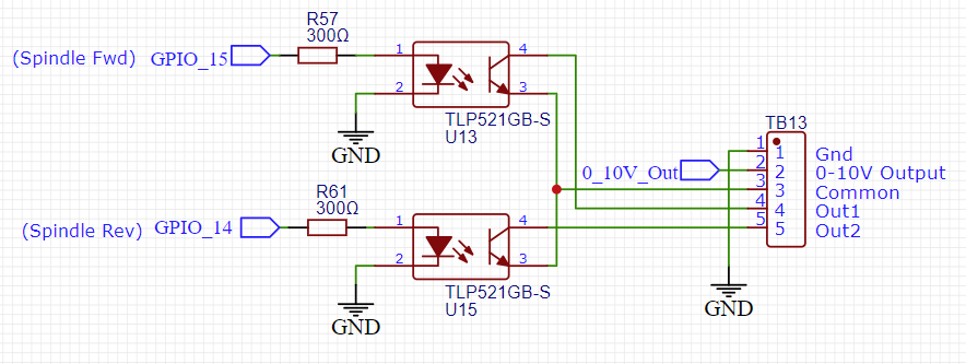
This uses an op-amp and a low pass filter to create an analog voltage. It can be adjusted with a trim pot for a max voltage of 5V to 10V. Measure and adjust the voltage before connecting to your spindle speed controller. A good way to do this is to send the gcode for max spindle speed like (M3 S24000 or whatever your max is) and then adjust the pot until you get the desired max voltage. It is best to set the max voltage before connecting to your VFD.
The schematic for the forward and reverse connections looks like this. They are isolated from the ESP32 and connect Out1 and Out2 to a common ground on the VFD.
Example Config section
10V:
  forward_pin: gpio.15
  reverse_pin: gpio.14
  pwm_hz: 5000
  output_pin: gpio.13
  enable_pin: NO_PIN
  direction_pin: NO_PIN
  disable_with_s0: false
  s0_with_disable: true
  spinup_ms: 0
  spindown_ms: 0
  tool_num: 0
  speed_map: 0=0.000% 1000=0.000% 24000=100.000%
  off_on_alarm: false
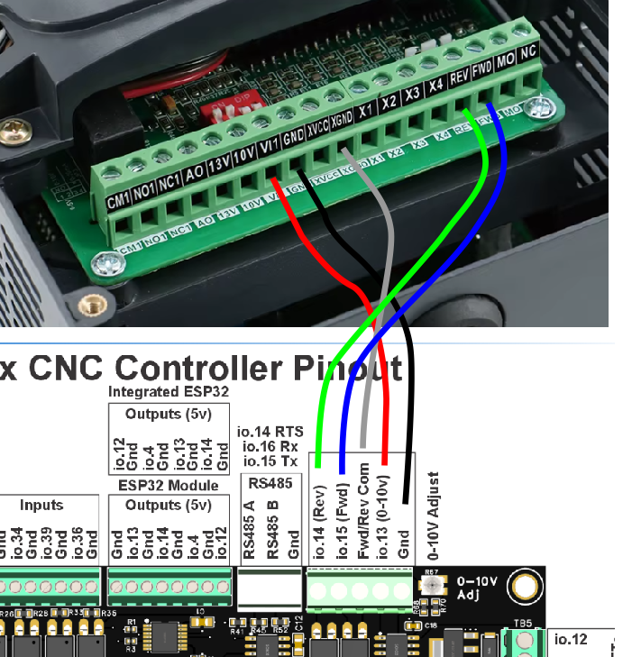
Here is an example of how to wire a Huanyang for 10V control. You aslo need to make sure all the registers are setup for 10V control.
YL620
Here is an example of how to wire a YL620 for 10V control. You aslo need to make sure all the registers are setup for 10V control.
P00.00 = 400 ( fq 400 hz )
P00.01 = 1
P07.08 = 3
P03.12 = 100 ( fq mini )
P03.13 = 400 ( fq maxi )
for the white dip switches in the red module above the green strip you have to put on "on" the 2 and the 4 (activation 10 volts of the Vfd) and leave on "off" the 1 and the 3
¶ Laser
The laser can be put on any of the 5V outputs. If you also want to use have another spindle type. Set that one up first and see what I/O is left.
¶ RS485
The RS485 circuit uses a MAX3485 chip. This requires the use a an rts_pin for data direction control.
There are LEDs to show and help debug communications issues.
- TX LED (labeled io15) You should see the TX blink a couple times per second. If you do not, something is wrong in your setup on the CNC controller side.
- Rx LED (labeled (RS485 Rx) The Rx should blink at the same rate (immediately after) as the Tx LED when communicating with the VFD. If the Rx LED stays on, try swapping the wires on the VFD side. If it does not light at all, there is probably a setup or other problem on the VFD side. Note: When no RS485 wires are connected the state of the LED is meaningless. Ignore that LED when not using RS485.
- RTS_LED (labeled i014) This should light the same time as the TX_LED.
Note: The circuit is a UART to RS485 converter. The LEDs represent the state of UART side IO. The idle state of a UART Tx is high, so the TX blinks are from on to off. The RTS LED will blink from off to on. It may be hard to see the Tx off blinks because the LED is bright and the off time is so brief. Try covering the other LEDs to see the blinks.
RS485 is a lot more complicated to setup than other types of spindles. It requires a lot of setup on the VFD side and good wiring. If you are having trouble, you should consider using the 0-10V method to control the spindle. It is very hard for us to support RS485 remotely.
Here is a typical RS485 config file section. This is specific to the 6x controller. You must also setup the VFD and get the wiring correct. For general information about VFD setup see the spindle wiki page.
For the my Huanyang, I connect the terminal labeled RS485 A on the controller to RS+ on the VFD and RS485 B on the controller to RS- on the VFD. I do not use the ground terminal.
# Begin Huanyang
uart1:
  txd_pin: gpio.15
  rxd_pin: gpio.16
  rts_pin: gpio.14
  baud: 9600
  mode: 8N1

Huanyang:
  uart_num: 1
  modbus_id: 1
  tool_num: 0
  speed_map: 0=0% 0=25% 6000=25% 24000=100%
  off_on_alarm: false
¶ MOSFETs
The (2) NPN MOSFETs are rated for 3A continuous and 5A peak. There are flyback diodes connected to VMot to make them safe for use with inductive loads, such as relays and solenoids.
The MOSFETs use gpio.4 and gpio.12. These I/O pins also activate 5V outputs.
The VMot terminals are always connected to VMot. Terminals labeled with the io pin numbers switch to ground when the io pins are active. If you need to operate devices with other voltages than VMot, you can use a separate DC power supply as long as it shares a common ground with the controller.
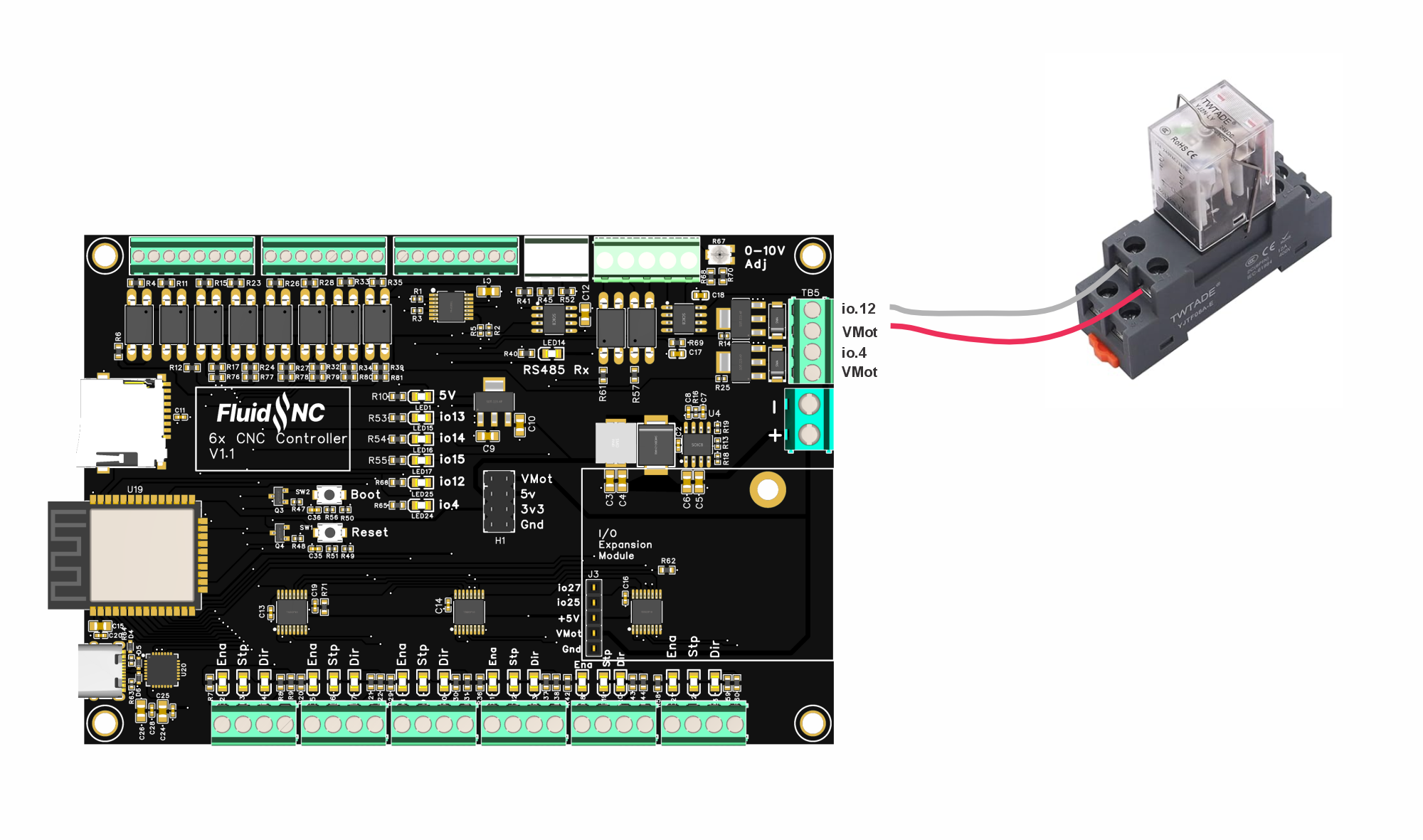
¶ Using Relays
There are three basic types of relays that are used in CNC. One is where you directly control the coil voltage. A second type is a relay mechanical where you only send a digital signal. The third is a solid state relay.
Switching mains voltage is inherently dangerous and should only be attempted by qualified people. In some countries, it is illegal for unlicensed people to perform mains wiring. Mains wiring should be inside rated enclosures for your jurisdiction.
¶ Directly controlling relay coils.
Relay coils pull too much current to be driven by the 5V output pins. You much connect them to the MOSFETs. Be sure the coil on the relay is design for the VMot voltage. The MOSFET circuit has a built in flyback diode, so you do not need to add one. If the relays have a built in didoe make sure you get the VMot on the correct side.
¶ Relay Circuits
Relay circuits control the power to a mechanical relay coil. You need to connect it to power (typically 5v), ground and a digital signal (3.3v or 5v usually work). Some circuits have several relays. You need to supply a ditital signal for each relay you want to control.
You can buy these 5v relays on amazon or aliexpress
Here is an example.
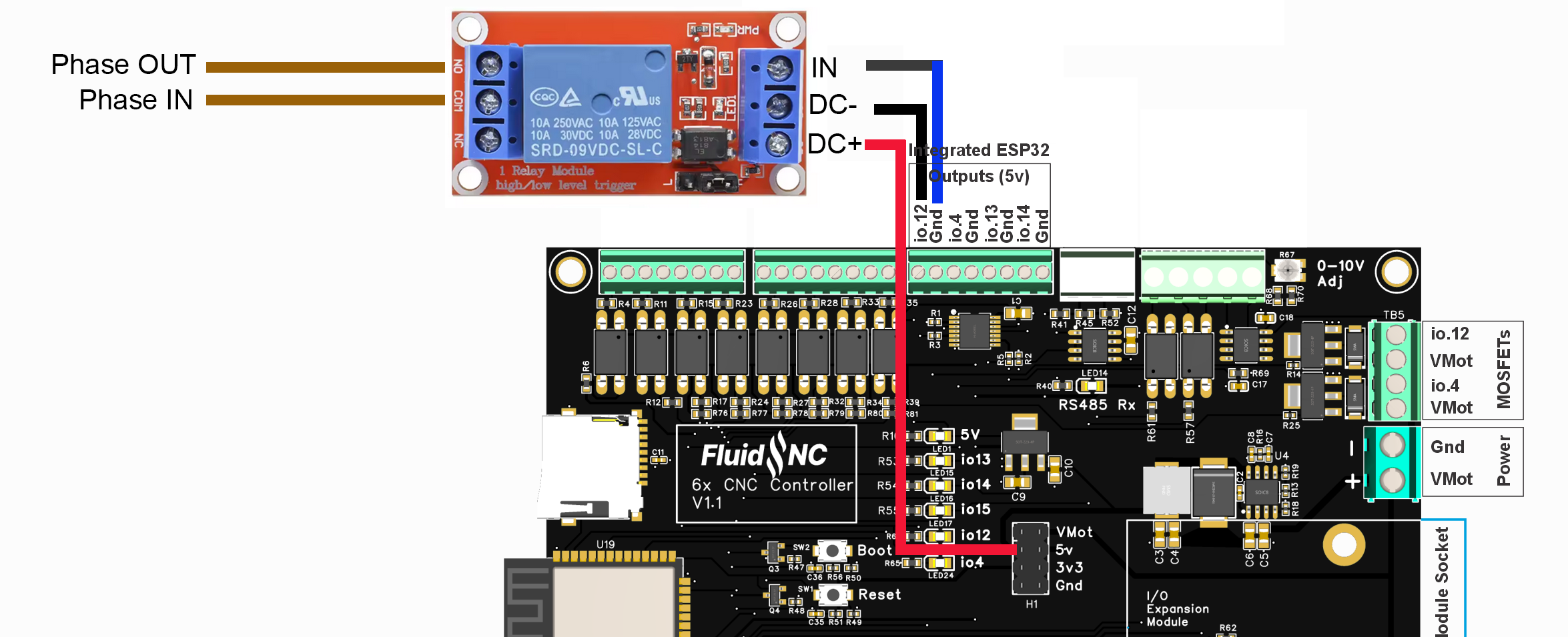
As an example, we'll activate a solenoid valve to lubricate the cutting tool of a cnc machine. You can connect any other component that respects the amperage and voltage of your relay.
Example of a code to activate the relay with the GRBL M8 command
coolant:
  flood_pin: gpio.12
  delay_ms: 0`
Any incorrect wiring can damage your 6x card. If you're unsure of your connections, we recommend testing with 5v or less (exemple switching on a 5v LED) by activating the relay.
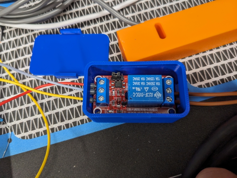
A user has provided this 3D-printed case for common relay modules. It is not a rated enclosure for mains wiring purposes.
¶ Solid State Relay
Solid state relays use electronic devices rather than a mechanical coil. They have several advantages. They have long life, silent operation, high current capability and can switch at a higher speed. You need to select different types depending on where you are switching AC or DC. You want it to have a DC input. The acceptible input range is typically quite wide like 3VDC - 32VDC.
They should be connected to a 5V output signal on the 6x.
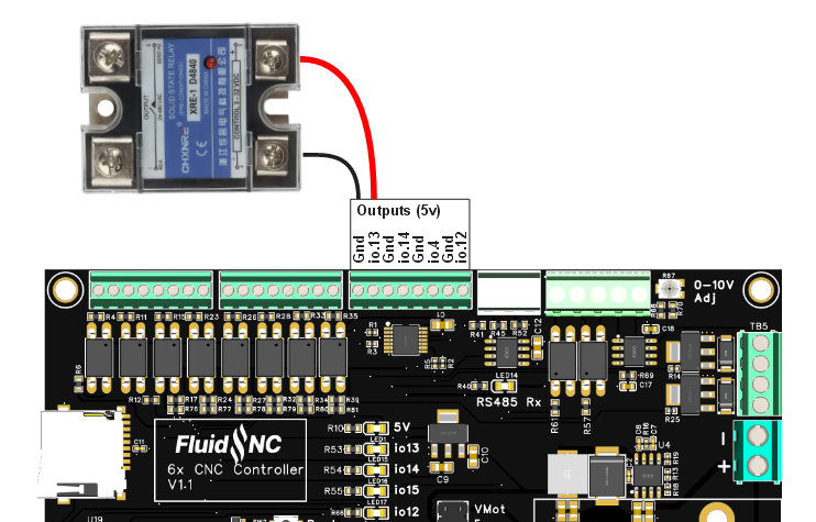
The solid state relay should be inside a rated enclosure that is wired according to regulatory codes for your jurisdiction.
For greater safety, we advise you to place it in an enclosure, as electricity passes through the screws and can be touched accidentally.
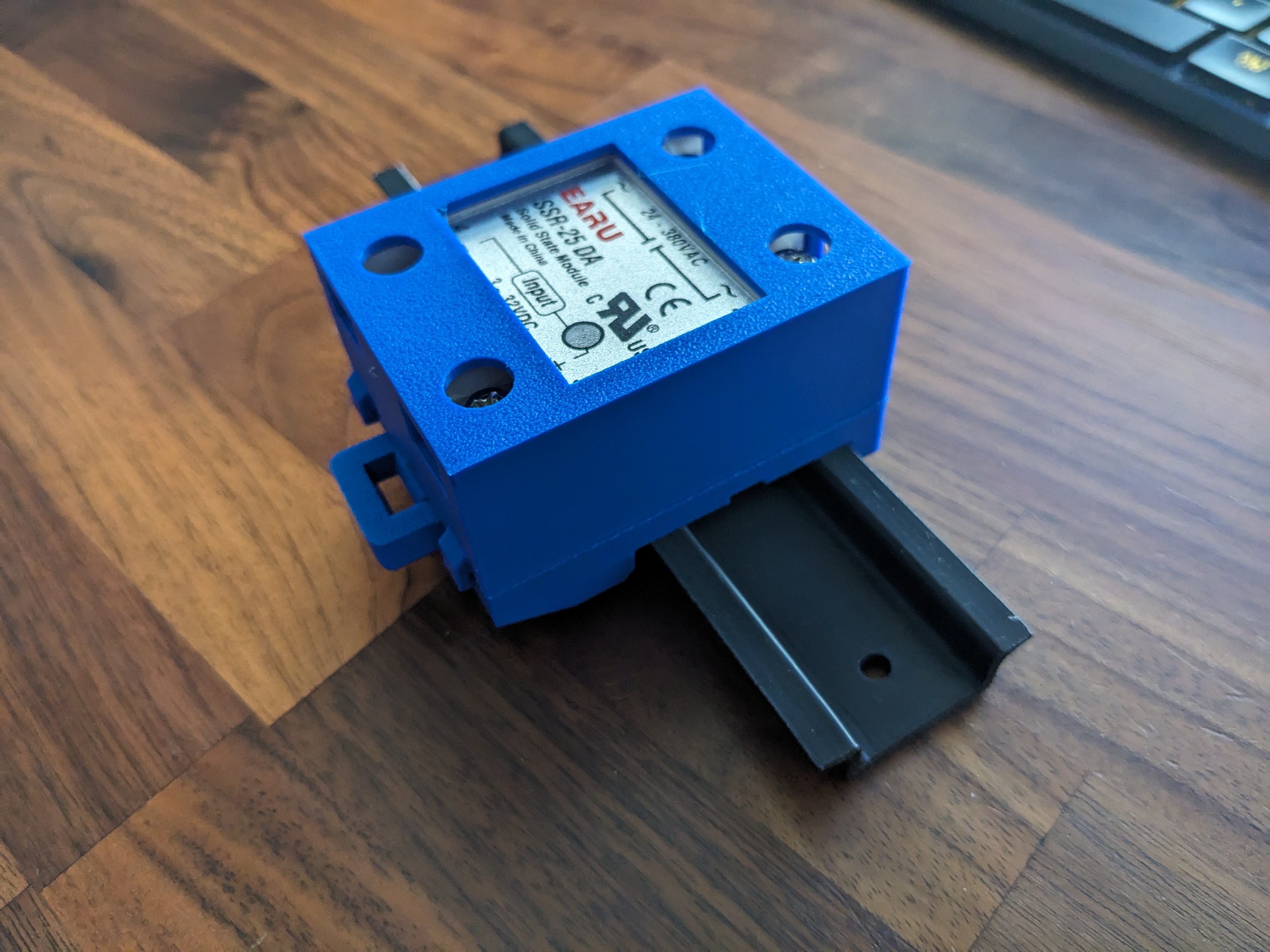
An enclosure for DIN rail mounting.
¶ RC Servo Usage
RC servos require one 5v PWM control signal. You can use any of the 5V outputs. You also need to power the servo. You can use the 5V pin in the center of the controller for most servos. If your servo requires more than about 1A, you might want to use a separate power supply that has a common ground with the controller.

  z:
    steps_per_mm: 100.000
    max_rate_mm_per_min: 5000.000
    acceleration_mm_per_sec2: 100.000
    max_travel_mm: 5.000
    soft_limits: true
    homing:
      cycle: 1
      positive_direction: true
      mpos_mm: 5.000

    motor0:
      rc_servo:
        pwm_hz: 50
        output_pin: gpio.12
        min_pulse_us: 1000
        max_pulse_us: 2000
¶ Expansion Module Socket
The socket is similar to the 6 pack modules except it only uses 2 I/O pins. You can partially use some 6 pack modules, but only the features that use the first 2 I/O pins. Examples: Relay module, 5V module (first 2 outputs only), Input module (first 2 inputs only).
You will need to provide a spacer to support the module. You can either use a 11mm long M3 threaded standoff or this 3D printed spacer (STL).
Here is a simple FluidDial module
You should only use modules that are designed for use with this controller. The socket pins connect directly to the ESP32 without any noise or ESD protection. The modules typically provide that protection. Directly wiring to the expansion socket will likely damage the controller.
Here are some modules you can use.
- Pendant Display Module
- 4x Input Module (only 2 inputs can be used)
- 5V Output Module (only 2 outputs can be used)
- MOSFET Module (only 2 outputs can be used)
- Isolated RS485 Module
- Relay Module
¶ Display or Pendant on the expansion connector.
Again...be very careful with the wiring.
Here is an example config file section
uart1:
  txd_pin: gpio.25
  rxd_pin: gpio.27
  rts_pin: NO_PIN
  cts_pin: NO_PIN
  baud: 1000000
  mode: 8N1

uart_channel1:
  report_interval_ms: 75
  uart_num: 1
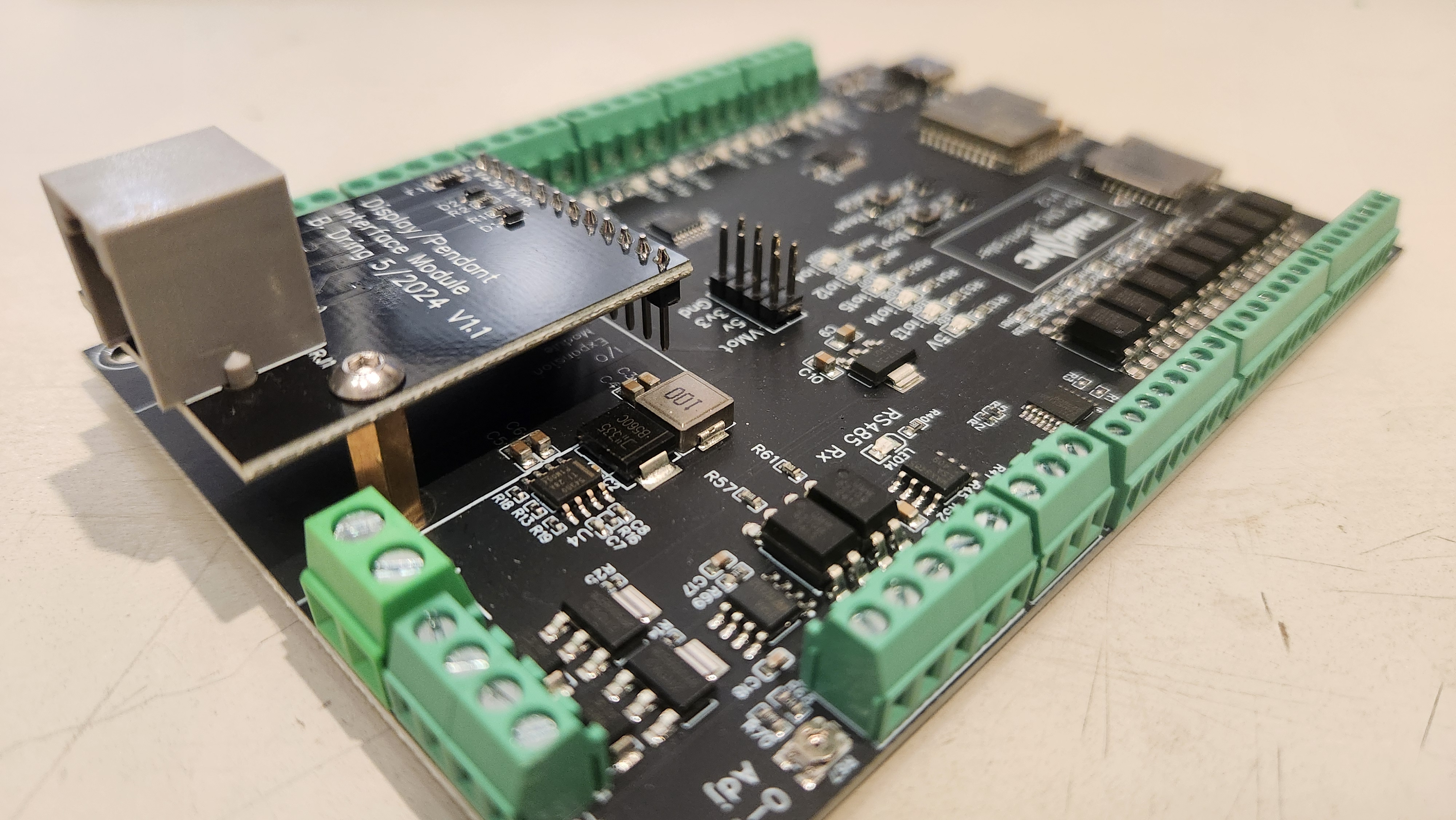
Here is a photo of the modulue mounted to the 6x Controller. The first 5 pins go into the socket. The rest are outside. They clear the components by several millimeters. You should mount the module using a screw and an 11mm spacer.
¶ Example Config File
Remove comment characters from the features you want to use, but be aware of not reusing io pins. You will see warnings in the start messages if that happens.
There is also a GitHub repo with some examples.
board: 6x
name: 6x Default
stepping:
  engine: I2S_STREAM
  idle_ms: 254
  pulse_us: 4
  dir_delay_us: 1
  disable_delay_us: 0

axes:
  shared_stepper_disable_pin: NO_PIN
  x:
    steps_per_mm: 800.000
    max_rate_mm_per_min: 5000.000
    acceleration_mm_per_sec2: 100.000
    max_travel_mm: 300.000
    soft_limits: false
    homing:
      cycle: 2
      positive_direction: false
      mpos_mm: 150.000
      feed_mm_per_min: 100.000
      seek_mm_per_min: 200.000
      settle_ms: 500
      seek_scaler: 1.100
      feed_scaler: 1.100

    motor0:
      limit_neg_pin: gpio.2:low:pu
      limit_pos_pin: NO_PIN
      limit_all_pin: NO_PIN
      hard_limits: false
      pulloff_mm: 1.000
      standard_stepper:
        step_pin: I2SO.2
        direction_pin: I2SO.1
        disable_pin: I2SO.0

  y:
    steps_per_mm: 800.000
    max_rate_mm_per_min: 5000.000
    acceleration_mm_per_sec2: 100.000
    max_travel_mm: 300.000
    soft_limits: false
    homing:
      cycle: 2
      positive_direction: true
      mpos_mm: 150.000
      feed_mm_per_min: 100.000
      seek_mm_per_min: 200.000
      settle_ms: 500
      seek_scaler: 1.100
      feed_scaler: 1.100

    motor0:
      limit_neg_pin: gpio.26:low:pu
      limit_pos_pin: NO_PIN
      limit_all_pin: NO_PIN
      hard_limits: false
      pulloff_mm: 1.000
      standard_stepper:
        step_pin: I2SO.5
        direction_pin: I2SO.4
        disable_pin: I2SO.7

  z:
    steps_per_mm: 800.000
    max_rate_mm_per_min: 5000.000
    acceleration_mm_per_sec2: 100.000
    max_travel_mm: 300.000
    soft_limits: false
    homing:
      cycle: 1
      positive_direction: true
      mpos_mm: 150.000
      feed_mm_per_min: 100.000
      seek_mm_per_min: 800.000
      settle_ms: 500
      seek_scaler: 1.100
      feed_scaler: 1.100

    motor0:
      limit_neg_pin: NO_PIN
      limit_pos_pin: gpio.33:low
      limit_all_pin: NO_PIN
      hard_limits: false
      pulloff_mm: 1.000
      standard_stepper:
        step_pin: I2SO.10
        direction_pin: I2SO.9
        disable_pin: I2SO.8

  a:
    steps_per_mm: 53.400
    max_rate_mm_per_min: 5000.000
    acceleration_mm_per_sec2: 100.000
    max_travel_mm: 960.000
    soft_limits: false
    homing:
      cycle: 2
      positive_direction: false
      mpos_mm: 150.000
      feed_mm_per_min: 100.000
      seek_mm_per_min: 200.000
      settle_ms: 500
      seek_scaler: 1.100
      feed_scaler: 1.100

    motor0:
      limit_neg_pin: gpio.32:low
      limit_pos_pin: NO_PIN
      limit_all_pin: NO_PIN
      hard_limits: false
      pulloff_mm: 3.000
      standard_stepper:
        step_pin: I2SO.13
        direction_pin: I2SO.12
        disable_pin: I2SO.15

  b:
    steps_per_mm: 808.000
    max_rate_mm_per_min: 5000.000
    acceleration_mm_per_sec2: 100.000
    max_travel_mm: 200.000
    soft_limits: false
    homing:
      cycle: 1
      positive_direction: false
      mpos_mm: 150.000
      feed_mm_per_min: 100.000
      seek_mm_per_min: 800.000
      settle_ms: 500
      seek_scaler: 1.100
      feed_scaler: 1.100

    motor0:
      limit_neg_pin: gpio.35:low
      limit_pos_pin: NO_PIN
      limit_all_pin: NO_PIN
      hard_limits: false
      pulloff_mm: 3.000
      standard_stepper:
        step_pin: I2SO.18
        direction_pin: I2SO.17
        disable_pin: I2SO.16

  c:
    steps_per_mm: 808.000
    max_rate_mm_per_min: 5000.000
    acceleration_mm_per_sec2: 100.000
    max_travel_mm: 200.000
    soft_limits: false
    homing:
      cycle: 1
      positive_direction: false
      mpos_mm: 150.000
      feed_mm_per_min: 100.000
      seek_mm_per_min: 800.000
      settle_ms: 500
      seek_scaler: 1.100
      feed_scaler: 1.100

    motor0:
      limit_neg_pin: gpio.34:low
      limit_pos_pin: NO_PIN
      limit_all_pin: NO_PIN
      hard_limits: false
      pulloff_mm: 3.000
      standard_stepper:
        step_pin: I2SO.21
        direction_pin: I2SO.20
        disable_pin: I2SO.23


i2so:
  bck_pin: gpio.22
  data_pin: gpio.21
  ws_pin: gpio.17

spi:
  miso_pin: gpio.19
  mosi_pin: gpio.23
  sck_pin: gpio.18

sdcard:
  card_detect_pin: NO_PIN
  cs_pin: gpio.5

probe:
  pin: gpio.39:low
  toolsetter_pin: gpio.36:low

# Using MOSFETs (Check Spindle Pin Usage
# coolant:
  # flood_pin: gpio.12
  # mist_pin: gpio.4
  # delay_ms: 0


start:
  must_home: false

# Begin Huanyang
uart1:
  txd_pin: gpio.15
  rxd_pin: gpio.16
  rts_pin: gpio.14
  baud: 9600
  mode: 8N1

Huanyang:
  uart_num: 1
  modbus_id: 1
  tool_num: 0
  speed_map: 0=0% 0=25% 6000=25% 24000=100%
  off_on_alarm: false

# #begin PWM
# pwm:
  # pwm_hz: 5000
  # direction_pin: NO_PIN
  # output_pin: gpio.13
  # enable_pin: gpio.14
  # disable_with_s0: false
  # s0_with_disable: true
  # spinup_ms: 0
  # spindown_ms: 0
  # tool_num: 0
  # speed_map: 0=0.000% 10000=100.000%
  # off_on_alarm: false

# #begin Laser
# Laser:
  # pwm_hz: 5000
  # output_pin: gpio.4
  # enable_pin: gpio.12
  # disable_with_s0: false
  # s0_with_disable: true
  # tool_num: 1
  # speed_map: 0=0.000% 255=100.000%
  # off_on_alarm: true

# #begin 10V
# 10V:
  # forward_pin: gpio.15
  # reverse_pin: gpio.14
  # pwm_hz: 5000
  # output_pin: gpio.13
  # enable_pin: NO_PIN
  # direction_pin: NO_PIN
  # disable_with_s0: false
  # s0_with_disable: true
  # spinup_ms: 0
  # spindown_ms: 0
  # tool_num: 0
  # speed_map: 0=0.000% 1000=0.000% 24000=100.000%
  # off_on_alarm: false
¶ Other Examples
¶ Genmitsu PROVerXL 4030
¶ Source Files
Everything is open source.
- PCB Schematic, Layout, & Fabrication Files (EasyEDA)
- 3D Models (GradCAD)
¶ Pinout Reference