¶ Airedale - FluidNC I/O Expander
¶ Overview
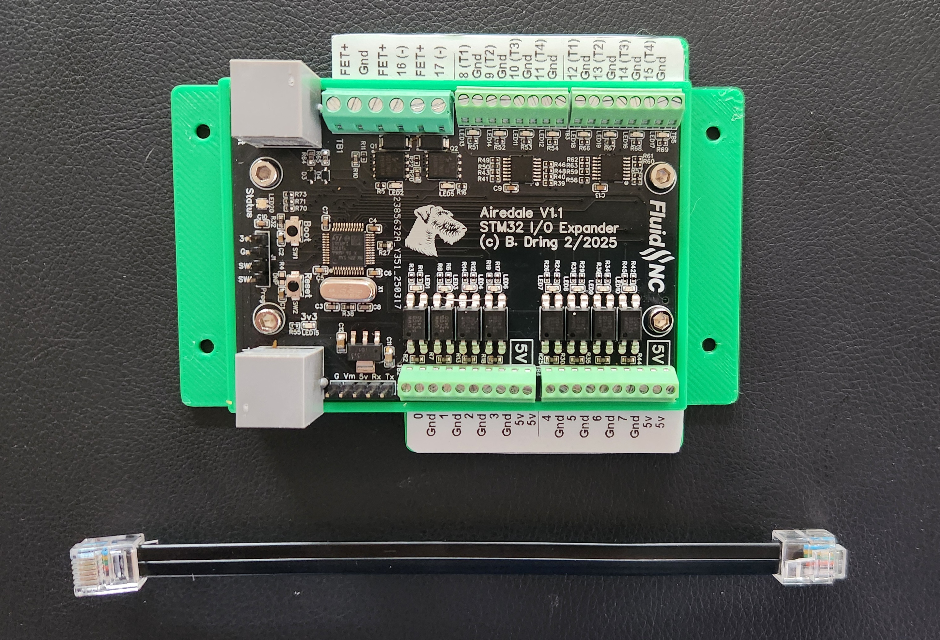
This device adds additional I/O pins to a FluidNC controller via a UART connection. It has inputs that can be used for switches. It also has outputs that can be digital or PWM.
The expander only works with FluidNC firmware v3.9.6 or later.
¶ How to get one.
¶ Features
- (8) Inputs
- (8) 5V outputs (digital or PWM)
- (2) MOSFETs (digital or PWM)
- LED indicators on all inputs and outputs.
- (1) UART Pass through
- RGB LED status indicator. This is used to show the status of the firmware during booting and can then be used as indicator by the user as output pins 18,19 and 20.
¶ Controller Compatibilty
It is designed to work with controllers that have RJ12 UART connectors. There are RJ12 modules for controllers that have CNC I/O Module sockets.
If you are already using a Pendant via RJ12, you can insert the Airedale between the controller and pendant.
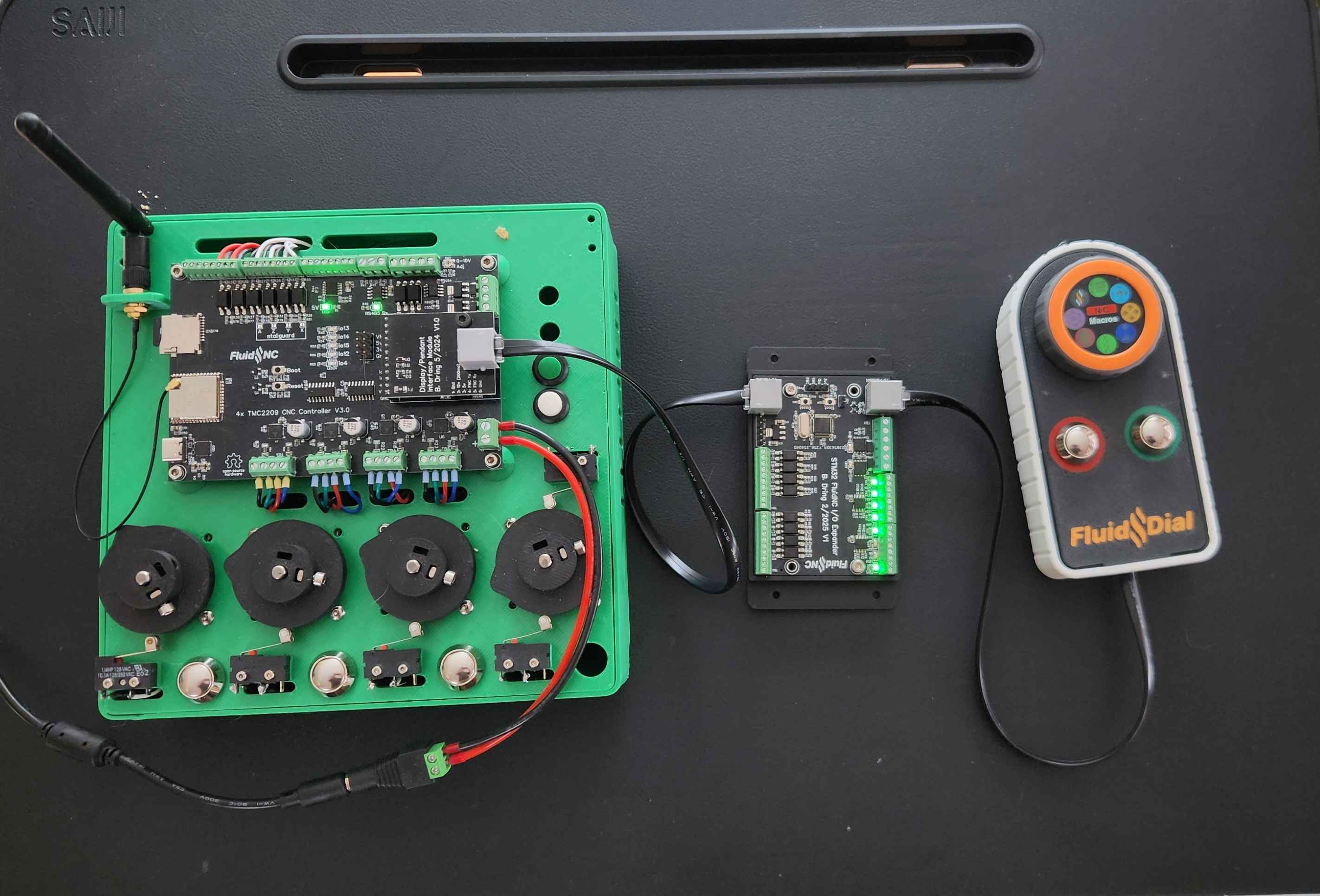
It is possible, but not recommended to connect it to controllers without RJ12 connectors. Any mistakes in wiring could break a lot of things. We cannot offer support to people trying this.
¶ Getting started
- Mount the Airedale so that any exposed pins on the bottom cannot contact anything and short. There is a 3D model of the Airedale and an example 3D printed case.
- With all power supplies off, connect the Airedale to your controller. Be sure to use the connector labeled "To FluidNC". It is strongly advised that you use a RJ12 cable and a controller with an RJ12 connector. This will prevent wiring mistakes that could destroy the Airedale and your controller.
- Add uart and uart_channel sections to your config file.
- Assigns pins to functions in your config file.
- If you have a uart based pendant or display, like the FluidDial, you can connect it to the other RJ12 connector labeled "To Pendant".
- Power on the main controller. It will power the Airedale. You should see the a green power LED light near the RJ12 connector and the RGB status LED should light with all colors on.
- Check your startup messages for errors.
¶ UART Pass through
This features allows you to add another UART channel device like a pendant or display. The expander filters out expander specific communication and sends the rest out the pass through port. All data received on the pass through is sent through the other UART to the FluidNC controller.
¶ Pin Numbers
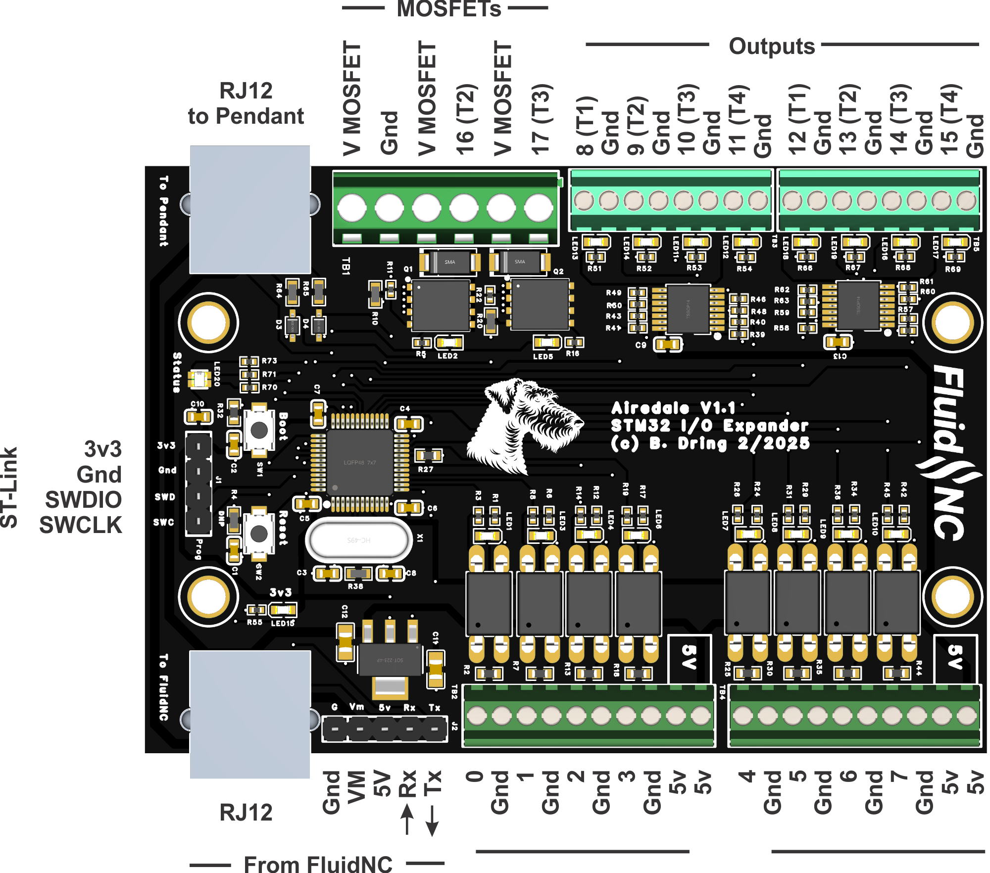
The pins are labeled with a number. This is the number you use in the config file. You specify the UART channel number and the pin number like:
safety_door_pin: uart_channel2.0:low
Note: This number has nothing to do with the STM32 pin numbers, Like A5, B11, etc. These are numbers assigned for the Airedale in the expander's firmware.
Be sure to only assign input pins to input functions and output pins to output functions. If you make a mistake, nothing will break, you just get a warning in your start messages.
¶ Inputs
All inputs go through opto isolators. You connect the input to ground to activate the input. They all have pull up resistor on the PCB. They are all active low. There are some 5V terminals you can use with powered switches. An LED associated with each input lights when the circuit is activated.
The inputs are uart_channelx.0: through uart_channelx.7
example
control:
  safety_door_pin: uart_channel2.0:low
Note: Type typical response time is less than a millisecond. You can use it for limit switches and probes.
¶ Outputs
The 5V outputs all go through 74AHCT125 buffers. They can each source and sink 25mA, but the total for each group of 4 is 50mA total.
The outputs cannot be used for motion control (stepper pins) or other very high speed, tightly coordinated control, like laser engraver power level.
The 5V outputs are uart_channelx.8 through uart_channelx.15 and the MOSFET outputs are uart_channelx.16 through uart_channelx.17
¶ PWM Limitations
The STM32 uses (4) timers for generating PWM frequencies. You can use any output pin for PWM, but you can only have (4) different frequencies.
The timers are wired to specific pins inside the STM32. All pins that share a timer must be on the same frequency. The controller is labeled with the pin numbers and the associated timer number. For example: the label 8 (T1) means this is pin 8 and uses timer 1. All pins with the same timer number must use the same frequency or your config will will give an alarm and load a default config.
¶ MOSFETs
The MOSFETs (HYG017N04LS1C2) are rated for 40V and lots of current. The max current is limited by the terminal block which is rated at 8A per terminal.
The 2 terminals near the RJ12 connector are for the MOSFET power input. The ground is common with common with the rest of the PCB.
¶ RJ12 UART Connections
The expander is designed to connect to the FluidNC controller using the standard RJ12 we use for pendants and displays. There is a module for this for controllers that support CNC I/O modules.
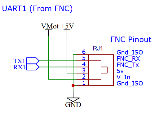
Controllers without an RJ12 option can be wired to the header next to the RJ12 connector. Be very careful with the wiring any mis-wire or electrical spikes will damage the expander and your FluidNC controller. The RJ12 modules have some protective circuitry. The Vm pin is only wired to the other RJ12 connector and can be used to power the attached display or pendant.
¶ RGB Status indicator
There is an RGB LED located near the pendant RJ12 connector. This is used to give basic operational status of the Airedale and can also be used as an output by the user.
Airedale Status (at startup)
- White (red, green & blue on) - Firmware has started, but FluidNC has not initialized the Airedale.
- Blue - Expander initialized
User determined status.
These can be used as digital (not PWM) outputs. The LED circuit is active low for all colors
- Red LED uart_channel<num>.18:low
- Green LED uart_channel<num>.19:low
- Blue LED uart_channel<num>.20:low
¶ Config file
You need to create a UART. The ESP32 has three (0, 1 & 2). The standard USB/Serial port uses 0, so you must use 1 or 2.
The baud for the extender is 1000000
The passthrough_baud should be 57600. In this case the passthrough is referring to passing data from the primary FluidNC serial port to the UART being defined. This is used when uploading firmware from FluidTerm.
If you are using a display or pendant on the second UART, you should have a report interval other than 0.
uart2:
  txd_pin: gpio.25
  rxd_pin: gpio.27
  baud: 1000000
  mode: 8N1
  passthrough_baud: 57600
  passthrough_mode: 8E1

uart_channel2:
  report_interval_ms: 75
  uart_num: 2
The order of the sections is important. Define the uart first, then the channel before assigning and pin numbers.
¶ Loading/Upgrading Firmware
Get the firmware file (firmware.bin). Go to the releases page page, download the zip file in the assets section of the latest release. Extract the firmware.bin to you computer.
There are 2 ways to load the firmware this.
¶ Via FluidTerm and the UART
Enter bootload mode by holding down the Boot button, clicking the reset button, then releasing the boot button. It will stay in boot mode until you click the reset button, so be sure to click the reset or power cycle after programming to exit bootloader mode.
¶ ST-Link Header
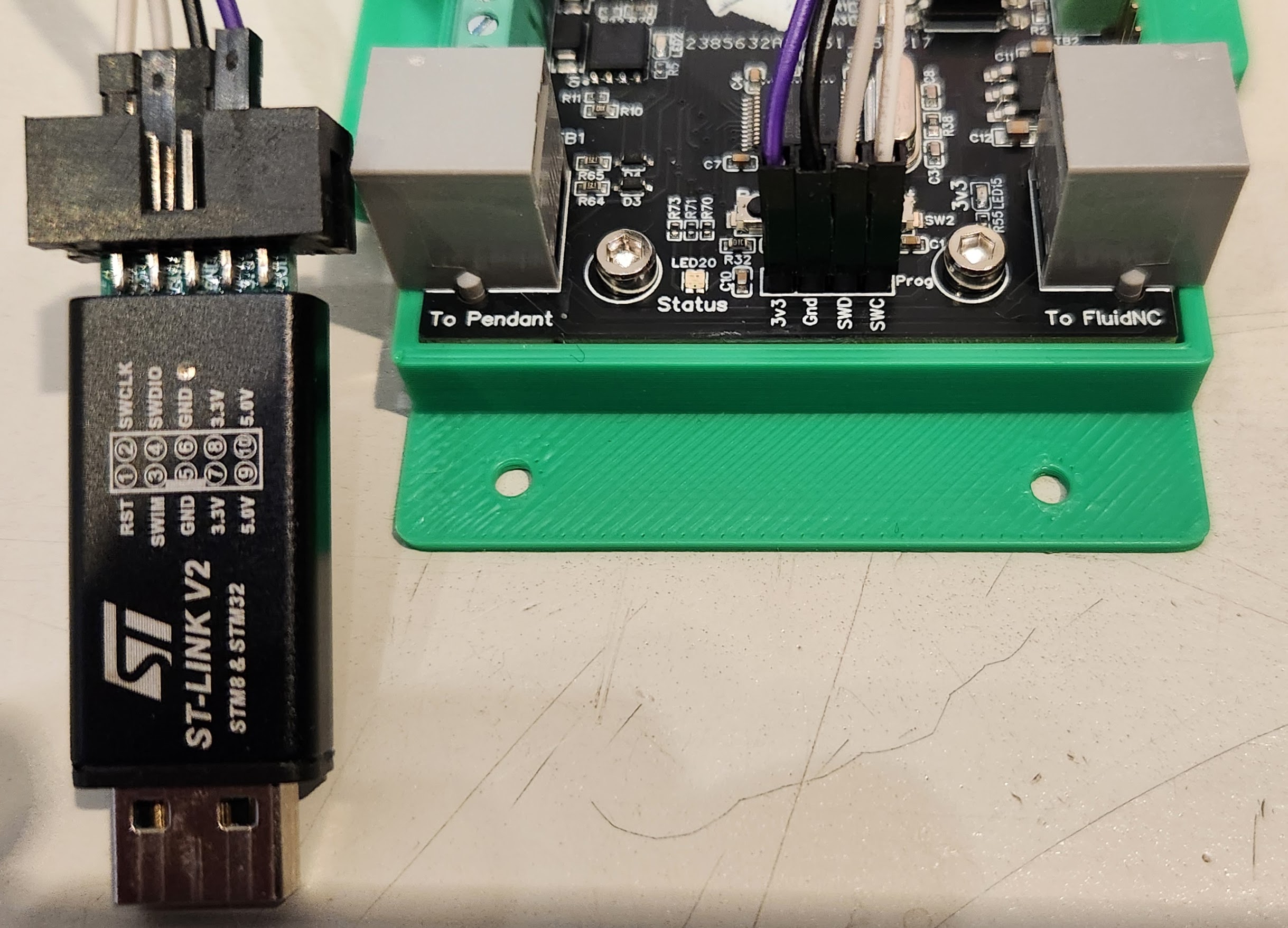
You need a programmer. The ST-Link V2 can be purchased for about $6 on Amazon.
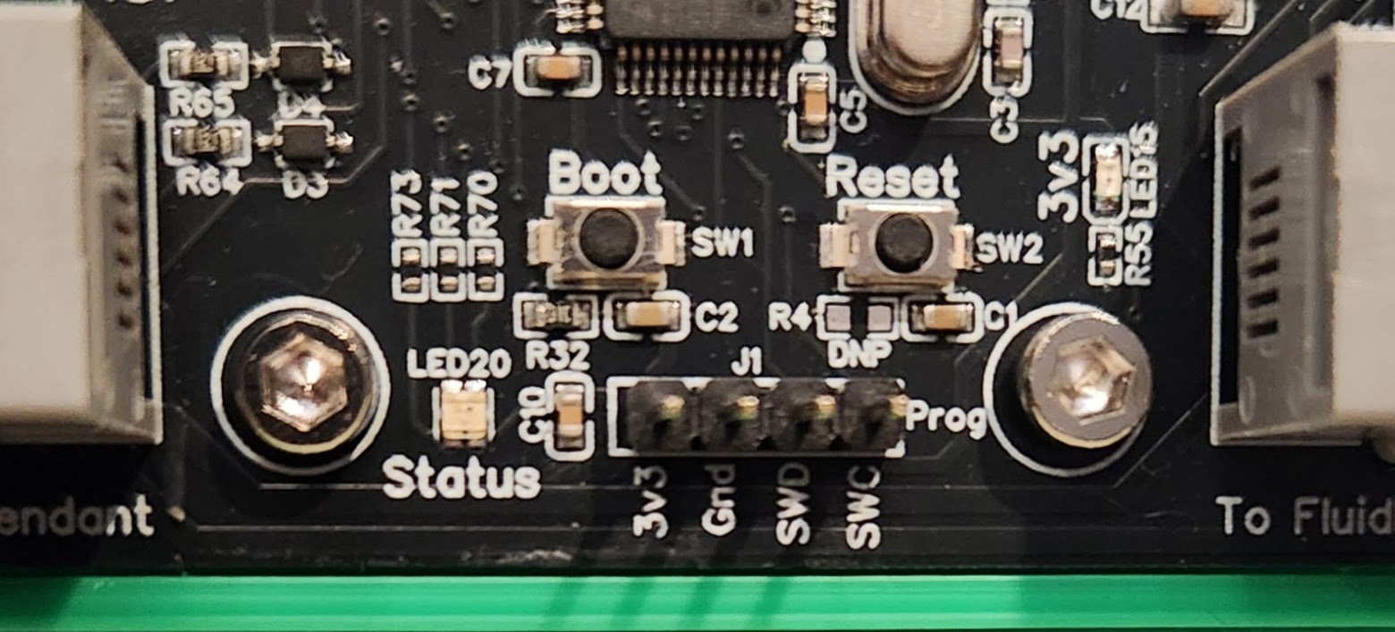
There is an ST-Link header connector on the Airedale. It ls located below the boot and reset buttons. Use the STM32 ST-Link Utility program. Connect the ST-Link as follows
ST-Link | Airdale
3.3V    | 3v3
GND     | Gnd
SWDIO   | SWD
SWCLK   | SWC
¶ Source Files
¶ Pinout
¶ Errata (known issues)
¶ V1.2 (current)
- The last 5V output is labeled 16, it should be 15. The pinout diagram is correct.
¶ V1.1
- All single color LEDs are red. They will be green in production
- Output #14 is not functional. The connection to the CPU is missing.