¶ Overview
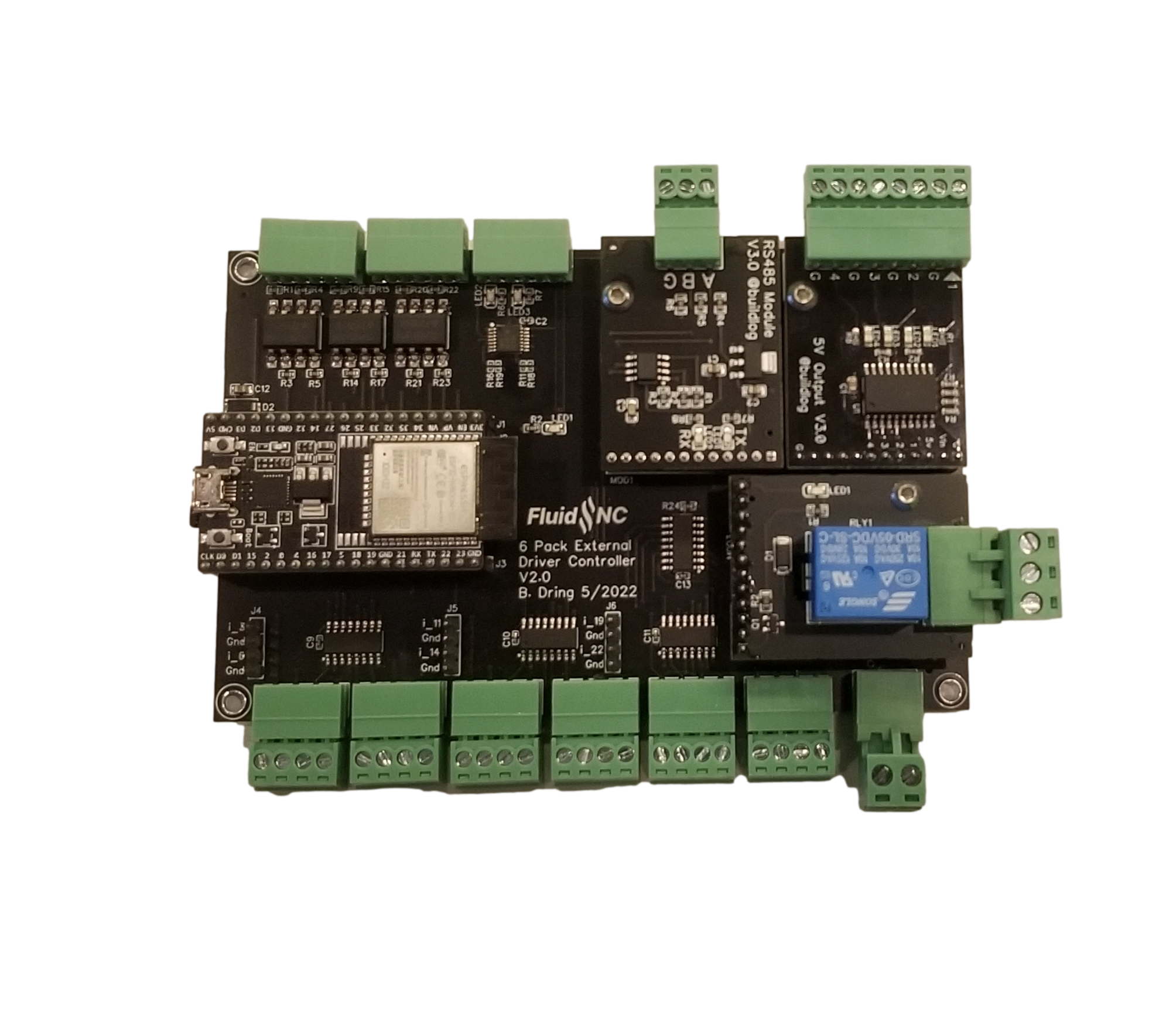
This is an external driver only CNC controller inspired by the 6 Pack controller.
¶ Features
- (6) External driver outputs. All pins can drive 5V opto inputs. Same pinout as the 6 Pack.
- (8) opto isolated inputs (saves buying 2 input modules)
- (2) built in 5V outputs.
- (2) GPIO CNC I/O module sockets (same pinout as 6 Pack). They are on the top edge of the board.
- (1) I2SO CNC I/O module socket (same pinout as 6 Pack). It is on the right edge of the board. These are output only pins.
- (6) additional I2SO outputs on header pins
- Compatible with all 6 pack modules. See the OSHW Labs page
¶ Source Files
The design is open source. The design files are in EasyEDA format which is a free online editor. It also allows people to order blank or assembled PCBs in low quantities at low cost with virtually no PCB design experience required.
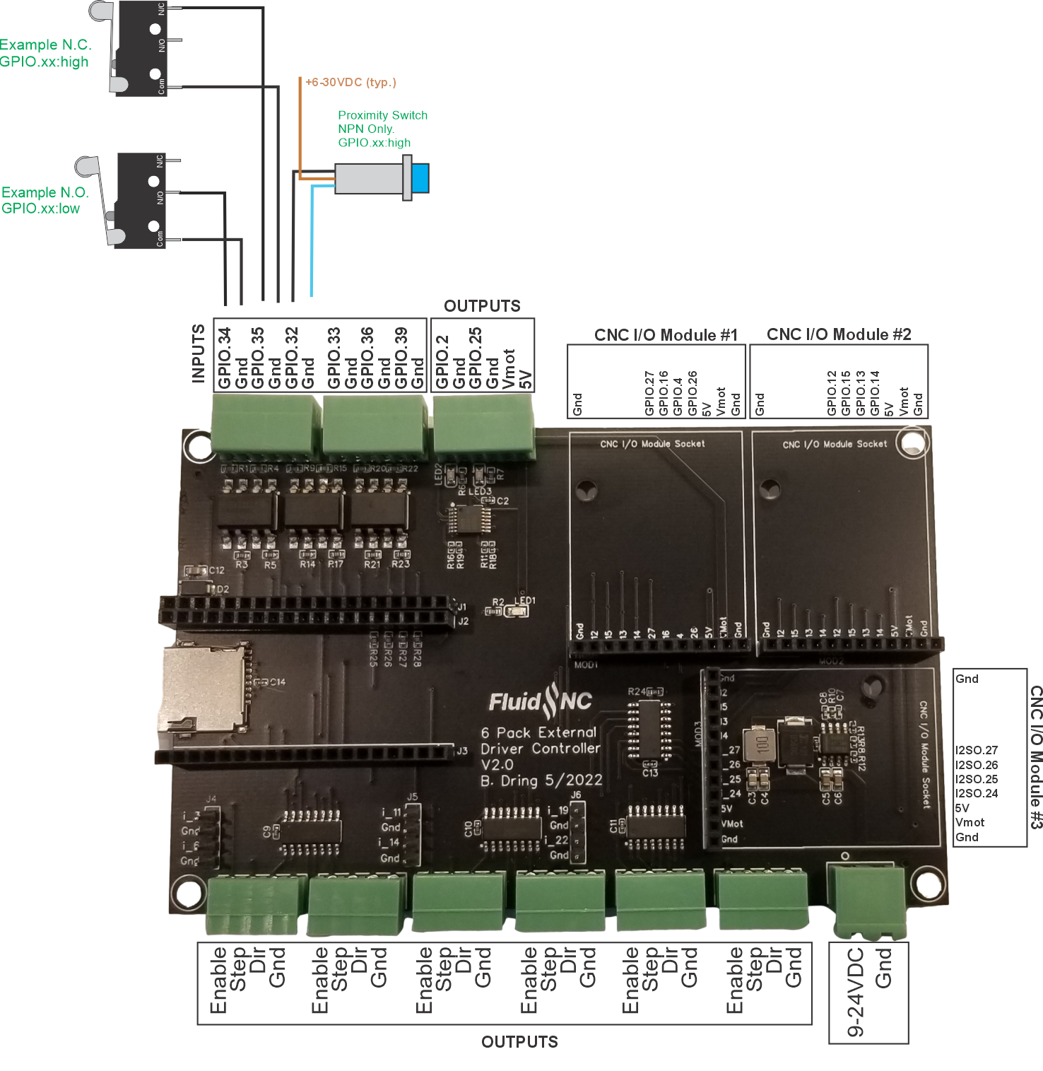
¶ Pinout
¶ Assembly
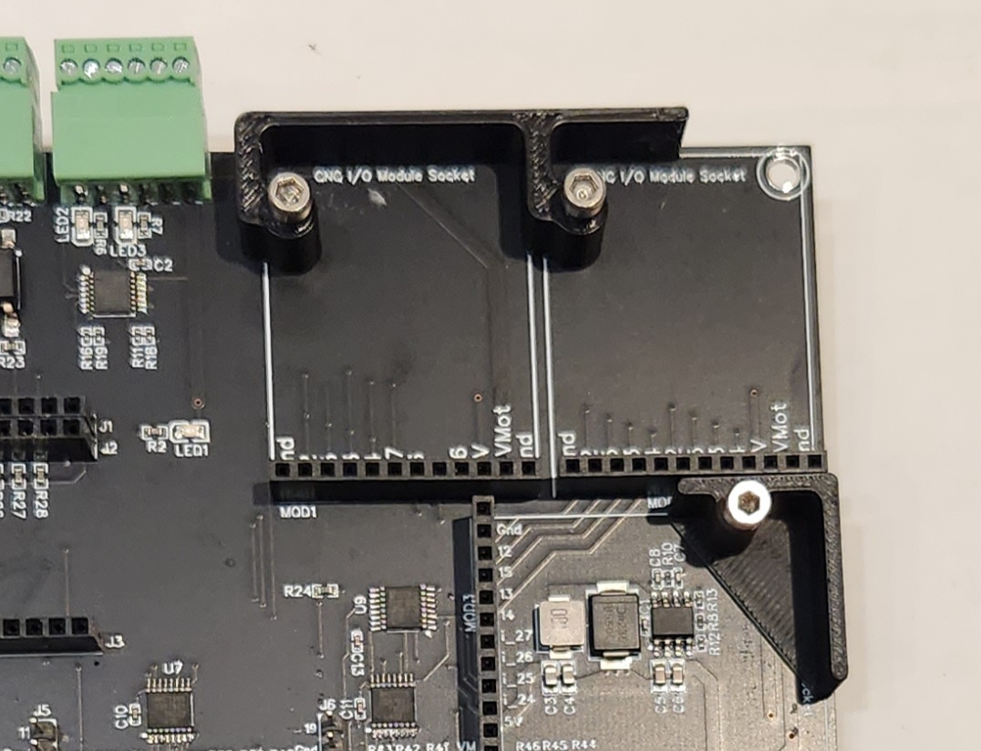
Install the module support peices as shown.
¶ ESP32 Module
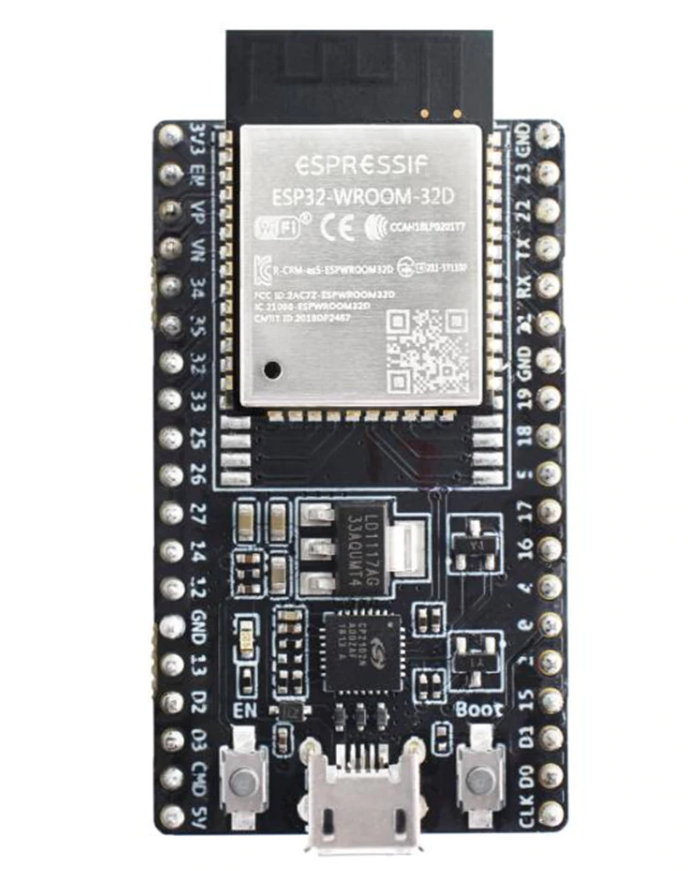
You must use the ESP32 module with the 38 pin (2 by 19) format. There is an extra connector to accomodate the narrow and wider format modules. The USB connector side faces toward the edge (not the middle) of the controller board (see view at top of page). There is more info on modules info here.
Here are some part numbers. Buy from a reputable supplier like Mouser or Digikey if you want official Espressif modules (about $10).
- ESP32-DevKitC-32E (Built in PCB Antenna)
- ESP32-DevKitC-32UE (Has external antenna connector)
¶ Config Information
¶ Inputs
Use the active low attribute, :low on all input pin. Use the pullup attribute,:pu, on pins 32 and 33. Pullup resistors are on the controller for 34,35,36 & 39.
gpio.32:low:pu
¶ Motor Driver Pins
The #n numbers represent the terminal blocks from left to right.
The diable_pin typically uses the :low attribute, because the driver has it as an enable imput.
These are all i2so pins. The i2so chip is a 74AHCT595. Each pin is rated for 20mA source/sink and 75mA total for the chip.
#1
      standard_stepper:
        step_pin: I2SO.2
        direction_pin: I2SO.1
        disable_pin: I2SO.0:low
#2
      standard_stepper:
        step_pin: I2SO.5
        direction_pin: I2SO.4
        disable_pin: I2SO.7:low
#3
      standard_stepper:
        step_pin: I2SO.10
        direction_pin: I2SO.9
        disable_pin: I2SO.8:low
#4
      standard_stepper:
        step_pin: I2SO.13
        direction_pin: I2SO.12
        disable_pin: I2SO.15:low
#5
      standard_stepper:
        step_pin: I2SO.18
        direction_pin: I2SO.17
        disable_pin: I2SO.16
#6
      standard_stepper:
        step_pin: I2SO.21
        direction_pin: I2SO.20
        disable_pin: I2SO.23:low
¶ Motor Driver Wiring
All motor driver pins can source (5v) and sink about 25mA each.
The wiring to the step/dir/enable terminals will be easiest if you use a common (-). Wire all the negative terminals on the driver to the GND on the controller terminal block. Wire all the (+) sides of the driver pins to the controller terminals labeled step/dir/enable. All drivers that use opto inputs should be able to use this wiring. It is much easier and safer to invert logic in firmware with the :low parameter than trying to do it in the wiring.
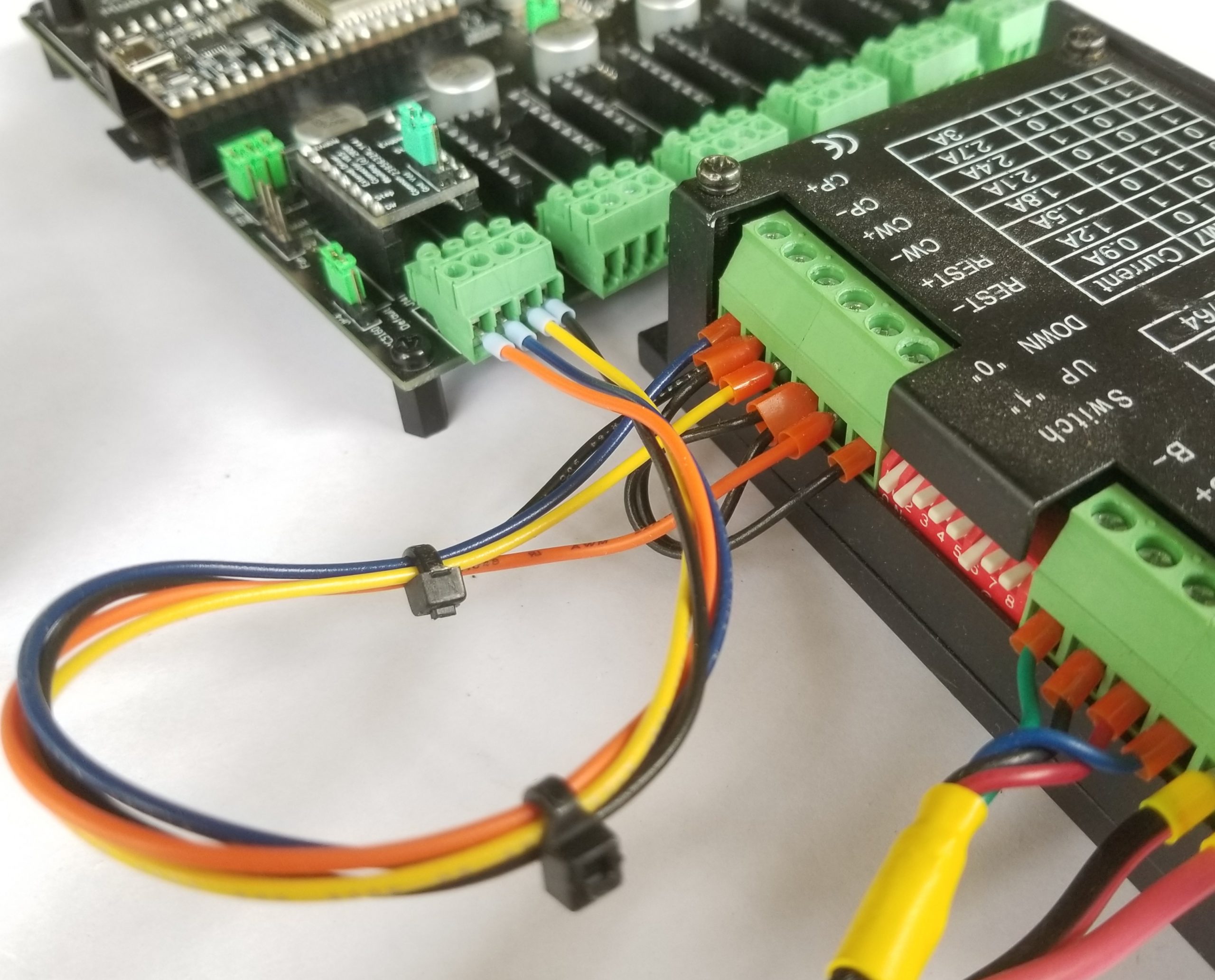
Here is a common ground connection example (from another controller). In this example the ground (black wire) goes from the controller's ground terminal to the step minus terminal (CP-). It then daisy chains the 2 other minus terminals (CW- and REST-), so they all get connected to the ground of the controller. The step, dir and enable terminals on the controller are wired to the CP+, CW+ and REST+ terminal respectively. Note these terminal may be labeled differently on your controller.
Only very experienced technicians should use the common pluse method. This is because you must source the the (+) voltage from other areas on the controller.
If you incorrectly wire the driver you could damage the controller and or damage the drivers. We will not provide tech support for the common plus this is for experts only.
¶ Switch Wiring
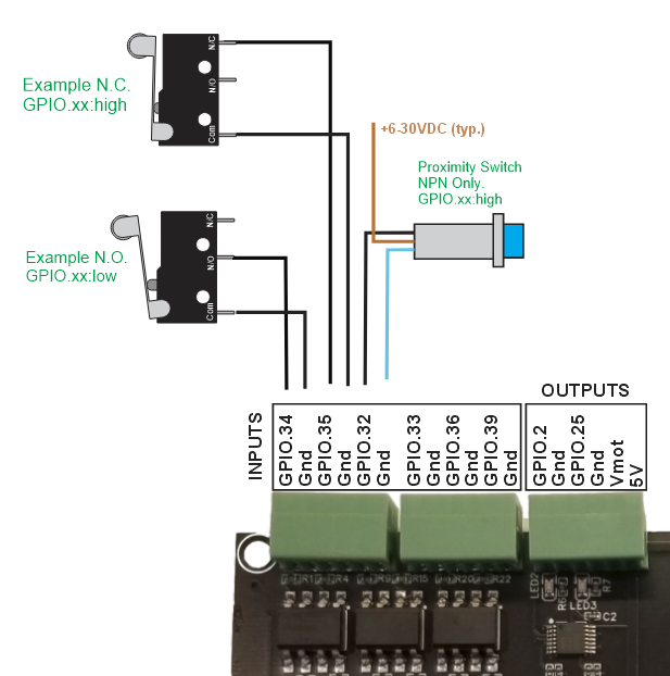
Here are some typical examples.
¶ 3D Models
¶ Programming Survey
¶ Programming Survey
If you ordered a programmed ESP32 with your controller via Tindie and want a custom configuration, please answer the questions on this survey.
This service is only designed to give you a head start on a known working and tested ESP32. You will need to edit the config file. It will likely take hours to finish and tune your machine.
The config will only cover the basic hardware and I/O. You will still need to fine tune the speeds, acceleration and motion ranges yourself.
Please do not send things like schematics, datasheets, protocols, etc. That goes way beyond the scope of this basic service.
Please copy the text below and place your answers after each question. Reply to to me via the Tindie message system.
- What is your name? (The Tindie messages do not show that to me)
- What is your Tindie order number?
- Motors
- How many motors are you using and what axes are they used for. Answer examples (XYZ, XYYZ, XXYYZ, etc). Max of 6 letter axes and 2 motors per axis. You will probably need to edit things like axis direction, speeds, accelration, axis range and possibly things like step pulse lengths yourself.
- Switches (only specify as many as you have inputs for)
- Limit switches
- List all limit switches you are using. If there are 2 on an axis are they separate or wired to the same input ? Answer examples (X-min, X-max, Y-dual (wired together), Z-max).
- If an axis uses more than one switch, which direction does it home? (toward min or max end of travel)
- Are you using a Z Probe? If so, if it is more than just a touch plate send a link to it.
- List any other switches here (Reset, Feedhold, Run, etc)
- Limit switches
- Spindle
- What Type of Spindle and/or Laser are you using? I will provide a basic config to get it working. You may need to edit things like max speed, spin up/down delays, etc. I can only configure for the spindles FluidNC supports. See the spindles page of this wiki.
- Accessories
- Are there any accessories you want to control? (Vacuum, Coolant, etc)
- Unused Modules
- Did you purchase any modules that you do not plan to use right away?
- Networking.
- Do you want to use Bluetooth or Wifi?
- Is there anything I left out? Did you purchase any module for special use not covered above.
¶ Viewing your existing file.
¶ Via Serial Terminal
You can use a serial terminal such as FluidTerm to view the file. Send $Config/Filename to get the name of the config file, then send $LocalFS/Show=<filename> to show the contents. You can then cut and paste the the text into a text editor.
$config/Filename
$Config/Filename=fluidnc_pen_laser_2209.yaml
ok
$localfs/show=fluidnc_pen_laser_2209.yaml
name: TMC2209 XY Servo Laser
board: FluidNC Pen/Laser 2209
meta:
stepping:
  engine: RMT
  idle_ms: 255
...

ok
¶ Via WebUI
Got to the FluidNC tab. Click on the green folder icon (Manage Local Files) and download the file.
¶ Via XModem
¶ Example Config File
board: 6 Pack
name: 6 Pack External XYZABC PWM
meta: 2023-01-29 B. Dring
stepping:
  engine: I2S_STREAM
  idle_ms: 255
  pulse_us: 4
  dir_delay_us: 1
  disable_delay_us: 0

axes:
  shared_stepper_disable_pin: NO_PIN
  x:
    steps_per_mm: 100.000
    max_rate_mm_per_min: 5000.000
    acceleration_mm_per_sec2: 100.000
    max_travel_mm: 300.000
    soft_limits: false
    homing:
      cycle: 2
      positive_direction: true
      mpos_mm: 0.000
      feed_mm_per_min: 100.000
      seek_mm_per_min: 200.000
      settle_ms: 500
      seek_scaler: 1.100
      feed_scaler: 1.100

    motor0:
      limit_neg_pin: gpio.34:low
      limit_pos_pin: NO_PIN
      limit_all_pin: NO_PIN
      hard_limits: false
      pulloff_mm: 1.000
      standard_stepper:
        step_pin: I2SO.2
        direction_pin: I2SO.1
        disable_pin: I2SO.0:low

  y:
    steps_per_mm: 100.000
    max_rate_mm_per_min: 5000.000
    acceleration_mm_per_sec2: 100.000
    max_travel_mm: 300.000
    soft_limits: false
    homing:
      cycle: 3
      positive_direction: false
      mpos_mm: 0.000
      feed_mm_per_min: 100.000
      seek_mm_per_min: 200.000
      settle_ms: 500
      seek_scaler: 1.100
      feed_scaler: 1.100

    motor0:
      limit_neg_pin: gpio.35:low
      limit_pos_pin: NO_PIN
      limit_all_pin: NO_PIN
      hard_limits: false
      pulloff_mm: 1.000
      standard_stepper:
        step_pin: I2SO.5
        direction_pin: I2SO.4
        disable_pin: I2SO.7:low

  z:
    steps_per_mm: 100.000
    max_rate_mm_per_min: 5000.000
    acceleration_mm_per_sec2: 100.000
    max_travel_mm: 150.000
    soft_limits: false
    homing:
      cycle: 1
      positive_direction: true
      mpos_mm: 150.000
      feed_mm_per_min: 100.000
      seek_mm_per_min: 800.000
      settle_ms: 500
      seek_scaler: 1.100
      feed_scaler: 1.100

    motor0:
      limit_neg_pin: gpio.32:low
      limit_pos_pin: NO_PIN
      limit_all_pin: NO_PIN
      hard_limits: false
      pulloff_mm: 1.000
      standard_stepper:
        step_pin: I2SO.10
        direction_pin: I2SO.9
        disable_pin: I2SO.8:low

  a:
    steps_per_mm: 100.000
    max_rate_mm_per_min: 5000.000
    acceleration_mm_per_sec2: 100.000
    max_travel_mm: 150.000
    soft_limits: false
    homing:
      cycle: 1
      positive_direction: true
      mpos_mm: 150.000
      feed_mm_per_min: 100.000
      seek_mm_per_min: 800.000
      settle_ms: 500
      seek_scaler: 1.100
      feed_scaler: 1.100

    motor0:
      limit_neg_pin: gpio.33:low
      limit_pos_pin: NO_PIN
      limit_all_pin: NO_PIN
      hard_limits: false
      pulloff_mm: 1.000
      standard_stepper:
        step_pin: I2SO.13
        direction_pin: I2SO.12
        disable_pin: I2SO.15:low

  b:
    steps_per_mm: 100.000
    max_rate_mm_per_min: 5000.000
    acceleration_mm_per_sec2: 100.000
    max_travel_mm: 150.000
    soft_limits: false
    homing:
      cycle: 1
      positive_direction: true
      mpos_mm: 150.000
      feed_mm_per_min: 100.000
      seek_mm_per_min: 800.000
      settle_ms: 500
      seek_scaler: 1.100
      feed_scaler: 1.100

    motor0:
      limit_neg_pin: gpio.36:low
      limit_pos_pin: NO_PIN
      limit_all_pin: NO_PIN
      hard_limits: false
      pulloff_mm: 1.000
      standard_stepper:
        step_pin: I2SO.18
        direction_pin: I2SO.17
        disable_pin: I2SO.16:low

  c:
    steps_per_mm: 100.000
    max_rate_mm_per_min: 5000.000
    acceleration_mm_per_sec2: 100.000
    max_travel_mm: 150.000
    soft_limits: false
    homing:
      cycle: 1
      positive_direction: true
      mpos_mm: 150.000
      feed_mm_per_min: 100.000
      seek_mm_per_min: 800.000
      settle_ms: 500
      seek_scaler: 1.100
      feed_scaler: 1.100

    motor0:
      limit_neg_pin: gpio.39:low
      limit_pos_pin: NO_PIN
      limit_all_pin: NO_PIN
      hard_limits: false
      pulloff_mm: 1.000
      standard_stepper:
        step_pin: I2SO.21
        direction_pin: I2SO.20
        disable_pin: I2SO.23:low

probe:
  pin: gpio.16
  check_mode_start: true

i2so:
  bck_pin: gpio.22
  data_pin: gpio.21
  ws_pin: gpio.17

spi:
  miso_pin: gpio.19
  mosi_pin: gpio.23
  sck_pin: gpio.18

sdcard:
  card_detect_pin: NO_PIN
  cs_pin: gpio.5

start:
  must_home: false

PWM:
  pwm_hz: 5000
  output_pin: gpio.25
  enable_pin: gpio.2
  direction_pin: NO_PIN
  disable_with_s0: false
  s0_with_disable: true
  spinup_ms: 5
  spindown_ms: 3
  tool_num: 0
  speed_map: 0=0% 10000=100%