¶ Corgi CNC Controller
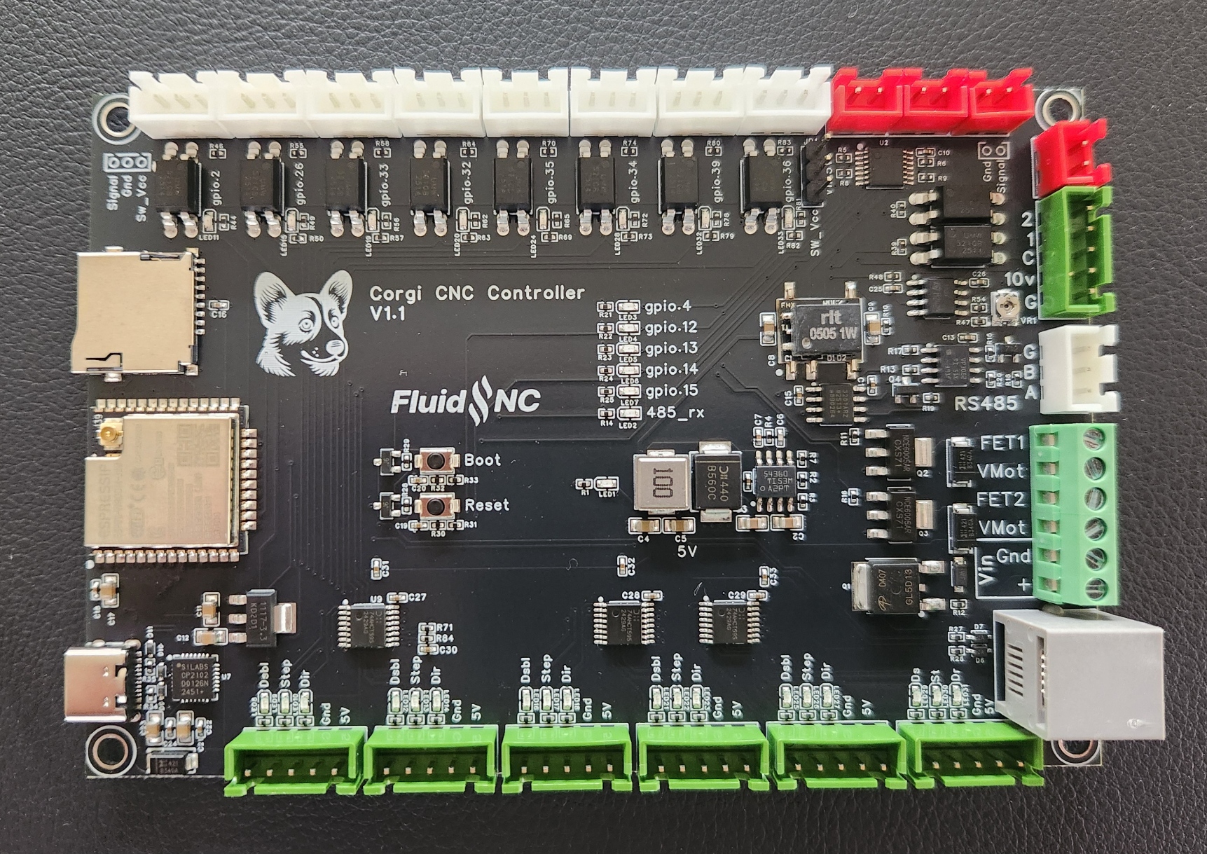
¶ Overview
This controller is similar to the 6x controller. It is designed for use with external stepper motor drivers. It incorporates a lot of suggestions from 6x users.
¶ Where to buy it
¶ Features
- Most connections use JST XH connectors. Only the connections that could exceed the current rating of those connectors are terminal blocks. (voltage in and MOSFETs). Some people prefer plug in connectors over terminal blocks. It makes it easier to temporarily unplug things or swap things around.,
- The main voltage input is reverse voltage protected. For simplicity, the main voltage is now 12V only.,
- The USB can now power the ESP32 if there is no main voltage in. This can be used to set up the controller. Several things (0-10v, FETs, pendants) on the controller require the main voltage and will not function properly without it.,
- RS485 is now fully isolated. It has also auto direction control, so only 2 I/O are required (TX and RX),
- Built in RJ12 for pendants and expanders.,
- (8) Inputs
- 3 pin XH connectors, ground, signal and SW_Vcc,
- SW_Vcc selectable between 5v and 12v. One selector affects all inputs,
- All have LEDs to indicate when they are activated.,
- Reverse voltage protection.,
- (6) External motor driver connectors. Each connector has 5v and Gnd to make it easy to use common ground,
- (4) 5V digital outputs,
- (2) 3A MOSFETs
Note: The ESP32 has limited gpio pins. To make the controller as flexible as possible some pins are wired to multiple features. For example gpio.4 can be used for a 5V digital output or a MOSFET. When you use the pin both features will activate. You can only assign the pin to one item in the config file.
¶ Versions
- The current version 1.1
¶ Getting Started
The controller ships with a version of FluidNC that was current when the controller was built. You upgrade the firmware using the web installer.
- Do not install your config file yet.
- Do not connect any external devices yet.
- Connect the antenna. You should only operate when the antenna is connected. A missing antenna can cause the ESP32 chip to overheat.
- Connect main power. Be sure the polarity is correct before you turn on the power.
- Turn on the main power and confirm that the 5v LED (red, near the center of the PCB) is lit.
- Connect a USB-C cable between your computer and the controller. Check to see that your computer has added a serial port.
- Go to the web installer. Connect to your controller and do an upgrade.
- You may want to connect to your wifi at this time.
- Now create and load a config file for your machine.
- Power down and connect all your devices. It might be helpful to connect just a few at a time and test as you go.
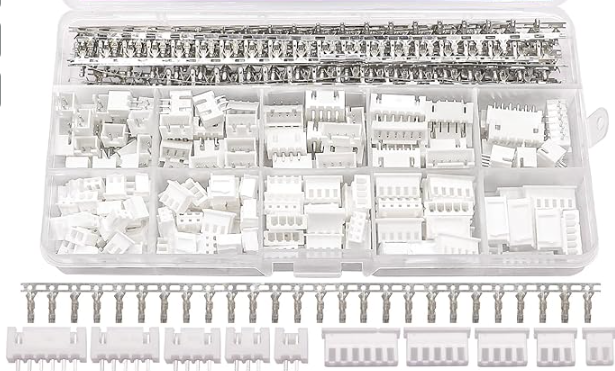
¶ Mating connectors
The mating connectors are female JST XH (2.54mm) 2, 3 and 5 pin connectors. They are not provided. A complete kit is easily found on Amazon (~$10), AliExpress or other places. Be sure to get a high quality crimping tool, if you do not have one. Search for "JST XH connector kit"
¶ Power
¶ Main power
The controller should be powered by 12V. I recommend a minimum of about 3A. It should be connected to the "Vin" pins on the 6 pin green terminal block. Double check the polarity before powering on. There is reverse polarity protection.
On the schematic and documatation you may see references to VMot, Vin. These are all connected to the 12V.
Note: The voltage range is limited to 12V on this controller to allow for better parts optimization. You will probably need to use a separate power supply for the motor drivers. If your drivers use opto isolators for the signals you should not use a common ground between the motor power supply and the controller power supply to insure best noise isolation.
¶ USB Power
You can power a few things with the USB connect. This can be helpful during setup and configuration. Much of the rest of the controller will not work without the main power on. The USB connection is not required during normal operation.
If you want to remove the ability for the USB to power the controller you can desolder the diode (D8) in the lower left corner of the controller.
¶ Power LED
A red LED will light in the center of the conntroller when power is properly applied. Depending on the state of the controller other LEDs may also light or blink.
¶ Programming
The controller comes with FluidNC installed and a basic config file. The version is probably not current, so you should do an upgrade via the Web Installer. Be sure to do an update rather than a full install or you will lose any existing config files.
If you are having trouble getting into bootloader mode, there are boot and reset buttons. To enter bootloader mode, hold the boot button, click reset and the release the boot button. This will enter the bootloader mode until the next reset.
¶ Motor driver outputs
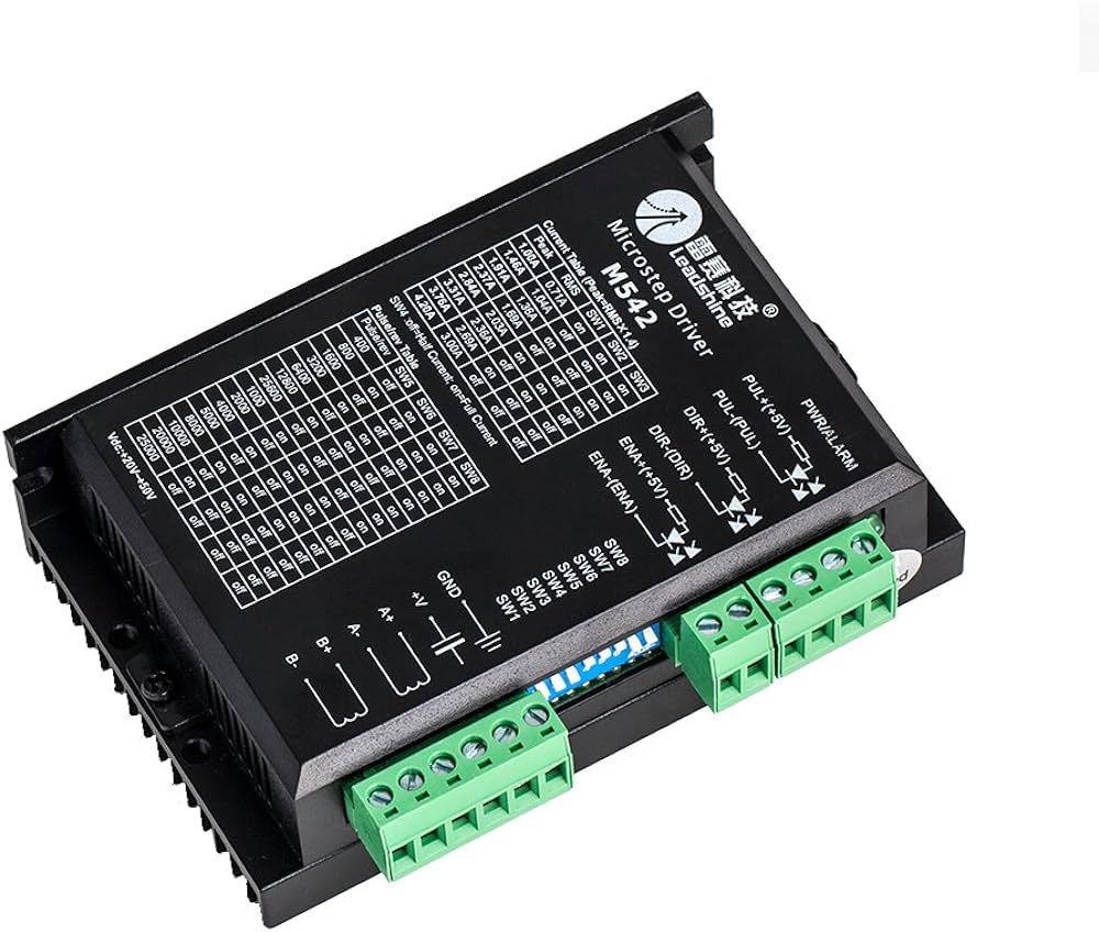
If you are not super familiar with external motor drivers or are having some issue, you should read this wiki page.
The controller is designed for use with external stepper driver modules that accept 5V step, direction, and enable signals. They all use i2so pins, so you need to use I2S_STATIC or I2S_STREAM in the stepping section of your config file.
stepping:
  engine: I2S_static
  idle_ms: 255
  pulse_us: 4
  dir_delay_us: 4
  disable_delay_us: 0
  segments: 6
Each connector has a disable signal, step signal, direction signal, gnd and 5V. You can either use gnd or 5V as the common pin.
Any motor output can be used for any axis or motor number. They are labeled Motor1 through motor6, just for reference. Here are the pins for each motors.
# motor 1
      standard_stepper:
        step_pin: I2SO.2
        direction_pin: I2SO.1
        disable_pin: I2SO.0

# motor2
      standard_stepper:
        step_pin: I2SO.5
        direction_pin: I2SO.4
        disable_pin: I2SO.7

# motor3
      standard_stepper:
        step_pin: I2SO.10
        direction_pin: I2SO.9
        disable_pin: I2SO.8

# motor4
      standard_stepper:
        step_pin: I2SO.13
        direction_pin: I2SO.12
        disable_pin: I2SO.15

# motor 5
      standard_stepper:
        step_pin: I2SO.18
        direction_pin: I2SO.17
        disable_pin: I2SO.16

# motor 6
      standard_stepper:
        step_pin: I2SO.21
        direction_pin: I2SO.20
        disable_pin: I2SO.23
¶ Motor driver wiring
Most external stepper drivers typically have 6 connections. These are 3 pairs (+ and -) for step, dir and enable. Step is often labeled pulse or pul. Each pair is for an optoisolator.
You can connect the signal to either the + or - side of the opto. The other side side of the opto would go the the gnd or +5v pins. You do not need to wire every motor signal with the same pattern. Do whatever is appropiate for each motor diver signal.
Most people wire ground to all the (-) pins to bnd and the signal pins to the (+) side. Any inversions needed can be done in firmware with the :high and :low pin configuration attributes.
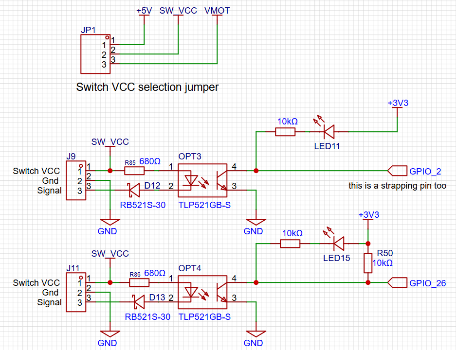
¶ Inputs
The input connectors are the 3 pin white connectors along the top edge. Each connector has a Switch Vcc, Gnd and signal pin. Switch Vcc is optional and used for switches that require power. Switch Vcc is selectable between Vin and 5v via a jumper near the right most input connector. You can also use external power for switches if a switch needs a special voltage.
All inputs activate by closing the signal to ground. You can use N.O. and N.C switch as long as one position closes to ground and will deliver enough current to light the opto LED. There is a reverse voltage protection diode for switches that have pullups in the inactive state.
All of the inputs have external pullup resistors except for gpio.2. You should add the :pu attribute when using that. gpio.2 is a strapping pin, so an external pullup cannot be used.
For normally open switches you need the *:low attribute on all inputs. Normally closed are active high. You can add the :high attribute, but it is not needed because that is default in FluidNC. The LED indicates when the circuit is closed. It will not match the "active" state of the FluidNC function if you use the :high attribute
Each input has an LED to show when the circuit is low state (signal connected to ground). This can be helpful to diagnose wiring issues. Note: If the gpio.2 input is not configured, the LED may light. Ignore it.
Be careful with switches that already have a 3 pin JST XH connector. The pinout is likely to be wrong. Double check that the switch pinout matches the Corgi pinout.
About the worst thing you can do is short Switch Vcc to ground. If your switch vcc is 5v it will probably just crash the controller.. If the switch vcc is 12V and you have a strong 12v power source, you might burn up some traces.
¶ NPN Sensor Wiring (Proximity, Inductive, etc)
You can use electronic switches like proximity or inductive switches as long as the output signal switches to ground when active (typically called NPN).
This is how to wire a typical proximity switch. Make sure your Vcc is compatible with the switch. If you don't have a compatible voltage on the Corgi, you can use an external power supply as long as there is a common ground.

¶ Outputs
¶ 5V outputs
The 5V outputs are on the (4) 2 pin red connectors. They can do digital or PWM. They are driven by a 74AHCT125 chip. They can do 20mA each, but only 50mA in total for all 4 outputs.
¶ MOSFETs
The (2) NPN MOSFETs are rated for 3A continuous and 5A peak. There are flyback diodes connected to VMot to make them safe for use with inductive loads, such as relays, small motors and solenoids.
The MOSFETs use gpio.4 and gpio.12. These I/O pins also activate 5V outputs.
The VMot terminals are always connected to 12V. Terminals labeled with the io pin numbers switch to ground when the io pins are active. If you need to operate devices with other voltages than 12v, you can use a separate DC power supply as long as it shares a common ground with the controller.
¶ Spindles
Many of the spindles share outputs with other features. Keep track of the I/O you are using to avoid conflicts.
¶ PWM
The PWM can be put on any of the 5V outputs.
example:
pwm:
  pwm_hz: 5000
  direction_pin: NO_PIN
  output_pin: gpio.13
  enable_pin: gpio.14
  disable_with_s0: false
  s0_with_disable: true
  spinup_ms: 0
  spindown_ms: 0
  tool_num: 0
  speed_map: 0=0.000% 10000=100.000%
  off_on_alarm: false
¶ 0-10V
This uses an op-amp and a low pass filter to create an analog voltage. It can be adjusted with a trim pot for a max voltage of 5V to 10V. Measure and adjust the voltage before connecting to your spindle speed controller. A good way to do this is to send the gcode for max spindle speed like (M3 S24000 or whatever your max is) and then adjust the pot until you get the desired max voltage. It is best to set the max voltage before connecting to your VFD.
Most VFDs have a 10V output. Do not connect this to the controller. Connect the 10V signal to the 10V input on the VFD.
The schematic for the forward and reverse connections looks like this. They are isolated from the ESP32 and connect Out1 and Out2 to a common ground on the VFD.
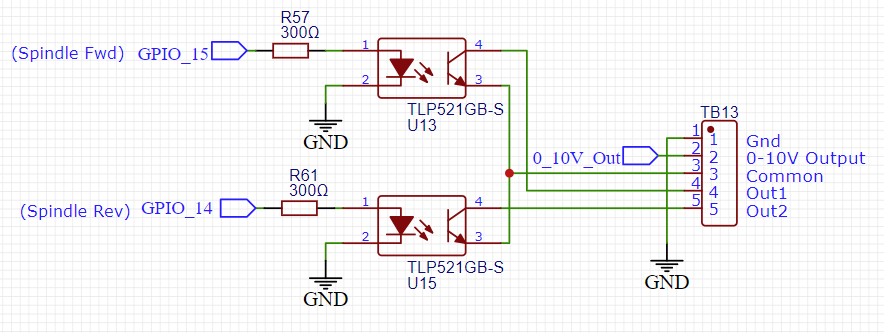
Example Config section
10V:
  forward_pin: gpio.15
  reverse_pin: gpio.14
  pwm_hz: 5000
  output_pin: gpio.13
  enable_pin: NO_PIN
  direction_pin: NO_PIN
  disable_with_s0: false
  s0_with_disable: true
  spinup_ms: 0
  spindown_ms: 0
  tool_num: 0
  speed_map: 0=0.000% 1000=0.000% 24000=100.000%
  off_on_alarm: false
¶ RS485
The RS485 circuit is fully isolated. It also has automatic direction control, so it does not use an rts_pin
There are LEDs to show and help debug communications issues.
- TX LED (labeled io15) You should see the TX blink a couple times per second. If you do not, something is wrong in your setup on the CNC controller side.
- Rx LED (labeled (RS485 Rx) The Rx should blink at the same rate (immediately after) as the Tx LED when communicating with the VFD. If the Rx LED stays on, try swapping the wires on the VFD side. If it does not light at all, there is probably a setup or other problem on the VFD side. Note: When no RS485 wires are connected the state of the LED is meaningless. Ignore that LED when not using RS485.
Note: The circuit is a UART to RS485 converter. The LEDs represent the state of UART side IO. The idle state of a UART Tx is high, so the TX blinks are from on to off. The RTS LED will blink from off to on. It may be hard to see the Tx off blinks because the LED is bright and the off time is so brief. Try covering the other LEDs to see the blinks.
RS485 is a lot more complicated to setup than other types of spindles. It requires a lot of setup on the VFD side and good wiring. If you are having trouble, you should consider using the 0-10V method to control the spindle. It is very hard for us to support RS485 remotely.
¶ RS485 Wiring
You should use 22-24AWG wires that are tightly twisted with at least 1 twist per inch. You can also use a twisted pair from some CAT5/6 cable.
You generally do not need a shield over the wires. If you do use a shield it should be grounded at the Corgi side. Do not connect the ground on the Corgi side to the VFD. This will defeat the isolation feature of the circuit.
VFDs are very noisy devices, especially the cheap ones. Some people have persistent communication problems that cannot be fixed.
¶ Config File
Here is a typical RS485 config file section. You must also setup the VFD and get the wiring correct. For general information about VFD setup see the spindle wiki page.
For the my Huanyang, I connect the terminal labeled RS485 A on the controller to RS+ on the VFD and RS485 B on the controller to RS- on the VFD. Most people should not use connect the ground terminal.
# Begin Huanyang
uart1:
  txd_pin: gpio.15
  rxd_pin: gpio.16
  baud: 9600
  mode: 8N1

Huanyang:
  uart_num: 1
  modbus_id: 1
  tool_num: 0
  speed_map: 0=0% 0=25% 6000=25% 24000=100%
  off_on_alarm: false
¶ Using external relays
¶ Relay circuits
¶ Directly controlling mechanical relays.
Relay coils pull too much current to be driven by the 5V output pins. You much connect them to the MOSFETs. Be sure the coil on the relay is design for the 12V. The MOSFET circuit has a built in flyback diode, so you do not need to add one. If the relays have a built in didoe make sure you get the VMot on the correct side.
For more info see the MOSFET section on this page.
¶ Solid State Relays
Solid state relays use electronic devices rather than a mechanical coil. They have several advantages. They have long life, silent operation, high current capability and can switch at a higher speed. You need to select different types depending on where you are switching AC or DC. You want it to have a DC input. The acceptible input range is typically quite wide like 3VDC - 32VDC.
They should be connected to a 5V output signal on the Corgi
¶ RC Servo Usage
RC servos require one 5v PWM control signal. You can use any of the 5V outputs. You also need to power the servo. This must be done with an external power source appropriate for the servo. It must have a common ground with the controller.
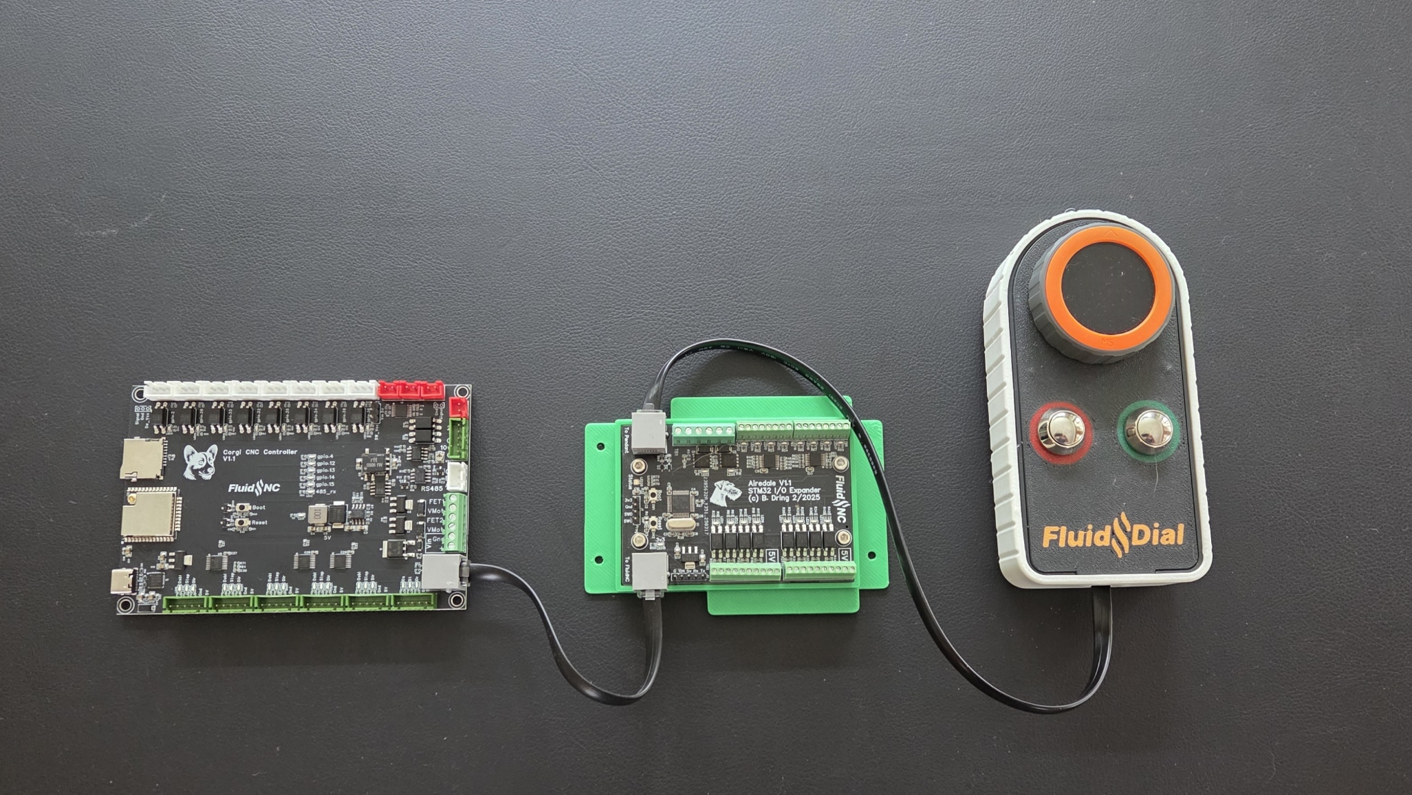
¶ Expansion connector
The expansion connector is an RJ12 jack. It is designed to be used with I/O exapnsion devices, like the Airedale and pendants like the FluidDial.
Here is an example config file section
# Begin expansion port uart and channel setup
uart2:
  txd_pin: gpio.27
  rxd_pin: gpio.25
  rts_pin: NO_PIN
  cts_pin: NO_PIN
  baud: 1000000
  mode: 8N1

uart_channel2:
  report_interval_ms: 75
  uart_num: 2
# End expansion port set up.
¶ Example config file
board: Corgi
name: Corgi Default
stepping:
  engine: I2S_STREAM
  idle_ms: 254
  pulse_us: 4
  dir_delay_us: 1
  disable_delay_us: 0

# Begin expansion port uart and channel setup
uart2:
  txd_pin: gpio.27
  rxd_pin: gpio.25
  rts_pin: NO_PIN
  cts_pin: NO_PIN
  baud: 1000000
  mode: 8N1

uart_channel2:
  report_interval_ms: 75
  uart_num: 2
# End expansion port set up.

axes:
  shared_stepper_disable_pin: NO_PIN
  x:
    steps_per_mm: 800.000
    max_rate_mm_per_min: 5000.000
    acceleration_mm_per_sec2: 100.000
    max_travel_mm: 300.000
    soft_limits: false
    homing:
      cycle: 2
      positive_direction: false
      mpos_mm: 150.000
      feed_mm_per_min: 100.000
      seek_mm_per_min: 200.000
      settle_ms: 500
      seek_scaler: 1.100
      feed_scaler: 1.100

    motor0:
      limit_neg_pin: gpio.2:low:pu
      limit_pos_pin: NO_PIN
      limit_all_pin: NO_PIN
      hard_limits: false
      pulloff_mm: 1.000
      standard_stepper:
        step_pin: I2SO.2
        direction_pin: I2SO.1
        disable_pin: I2SO.0

  y:
    steps_per_mm: 800.000
    max_rate_mm_per_min: 5000.000
    acceleration_mm_per_sec2: 100.000
    max_travel_mm: 300.000
    soft_limits: false
    homing:
      cycle: 2
      positive_direction: true
      mpos_mm: 150.000
      feed_mm_per_min: 100.000
      seek_mm_per_min: 200.000
      settle_ms: 500
      seek_scaler: 1.100
      feed_scaler: 1.100

    motor0:
      limit_neg_pin: gpio.26:low
      limit_pos_pin: NO_PIN
      limit_all_pin: NO_PIN
      hard_limits: false
      pulloff_mm: 1.000
      standard_stepper:
        step_pin: I2SO.5
        direction_pin: I2SO.4
        disable_pin: I2SO.7

  z:
    steps_per_mm: 800.000
    max_rate_mm_per_min: 5000.000
    acceleration_mm_per_sec2: 100.000
    max_travel_mm: 300.000
    soft_limits: false
    homing:
      cycle: 1
      positive_direction: true
      mpos_mm: 150.000
      feed_mm_per_min: 100.000
      seek_mm_per_min: 800.000
      settle_ms: 500
      seek_scaler: 1.100
      feed_scaler: 1.100

    motor0:
      limit_neg_pin: gpio.33:low
      limit_pos_pin: NO_PIN
      limit_all_pin: NO_PIN
      hard_limits: false
      pulloff_mm: 1.000
      standard_stepper:
        step_pin: I2SO.10
        direction_pin: I2SO.9
        disable_pin: I2SO.8

  a:
    steps_per_mm: 53.400
    max_rate_mm_per_min: 5000.000
    acceleration_mm_per_sec2: 100.000
    max_travel_mm: 960.000
    soft_limits: false
    homing:
      cycle: 2
      positive_direction: false
      mpos_mm: 150.000
      feed_mm_per_min: 100.000
      seek_mm_per_min: 200.000
      settle_ms: 500
      seek_scaler: 1.100
      feed_scaler: 1.100

    motor0:
      limit_neg_pin: gpio.32:low
      limit_pos_pin: NO_PIN
      limit_all_pin: NO_PIN
      hard_limits: false
      pulloff_mm: 3.000
      standard_stepper:
        step_pin: I2SO.13
        direction_pin: I2SO.12
        disable_pin: I2SO.15

  b:
    steps_per_mm: 808.000
    max_rate_mm_per_min: 5000.000
    acceleration_mm_per_sec2: 100.000
    max_travel_mm: 200.000
    soft_limits: false
    homing:
      cycle: 1
      positive_direction: false
      mpos_mm: 150.000
      feed_mm_per_min: 100.000
      seek_mm_per_min: 800.000
      settle_ms: 500
      seek_scaler: 1.100
      feed_scaler: 1.100

    motor0:
      limit_neg_pin: gpio.35:low
      limit_pos_pin: NO_PIN
      limit_all_pin: NO_PIN
      hard_limits: false
      pulloff_mm: 3.000
      standard_stepper:
        step_pin: I2SO.18
        direction_pin: I2SO.17
        disable_pin: I2SO.16

  c:
    steps_per_mm: 808.000
    max_rate_mm_per_min: 5000.000
    acceleration_mm_per_sec2: 100.000
    max_travel_mm: 200.000
    soft_limits: false
    homing:
      cycle: 1
      positive_direction: false
      mpos_mm: 150.000
      feed_mm_per_min: 100.000
      seek_mm_per_min: 800.000
      settle_ms: 500
      seek_scaler: 1.100
      feed_scaler: 1.100

    motor0:
      limit_neg_pin: gpio.34:low
      limit_pos_pin: NO_PIN
      limit_all_pin: NO_PIN
      hard_limits: false
      pulloff_mm: 3.000
      standard_stepper:
        step_pin: I2SO.21
        direction_pin: I2SO.20
        disable_pin: I2SO.23

i2so:
  bck_pin: gpio.22
  data_pin: gpio.21
  ws_pin: gpio.17

spi:
  miso_pin: gpio.19
  mosi_pin: gpio.23
  sck_pin: gpio.18

sdcard:
  card_detect_pin: NO_PIN
  cs_pin: gpio.5

probe:
  pin: gpio.39:low
  toolsetter_pin: gpio.36:low
  check_mode_start: true
  hard_stop: false

# coolant on the MOSFETs
coolant:
  flood_pin: gpio.12
  mist_pin: gpio.4

user_outputs:
  # analog0_pin: gpio.13
  # analog1_pin: gpio.14
  analog0_hz: 5000
  analog1_hz: 5000

# pwm:
  # pwm_hz: 5000
  # direction_pin: NO_PIN
  # output_pin: gpio.13
  # enable_pin: gpio.14
  # disable_with_s0: false
  # s0_with_disable: true
  # spinup_ms: 0
  # spindown_ms: 0
  # tool_num: 0
  # speed_map: 0=0.000% 10000=100.000%
  # off_on_alarm: false

# Begin Huanyang
# uart1:
  # txd_pin: gpio.15
  # rxd_pin: gpio.16
  # baud: 9600
  # mode: 8N1

# Huanyang:
  # uart_num: 1
  # modbus_id: 1
  # tool_num: 0
  # speed_map: 0=0% 0=25% 6000=25% 24000=100%
  # off_on_alarm: false
# End Huanyang

10V:
  forward_pin: gpio.15
  reverse_pin: gpio.14
  pwm_hz: 5000
  output_pin: gpio.13
  enable_pin: NO_PIN
  direction_pin: NO_PIN
  disable_with_s0: false
  s0_with_disable: true
  spinup_ms: 0
  spindown_ms: 0
  tool_num: 0
  speed_map: 0=0.000% 1000=0.000% 24000=100.000%
  off_on_alarm: false

start:
  must_home: false
¶ Open Source files
¶ Pinout reference
