¶ External Stepper Motor Drivers

External stepper motor drivers are typically used when you want more power than the the small plug-in drivers can supply. You can also get advanced features like closed loop stepper and servo motors.
As long as they accept step and direction signals, you can probably use them. They usually have an enable signal and some have a fault signal. FluidNC supports the enable signal, either on a per driver basis or a shared pin that controls all drivers. It also supports the fault output on a shared basis, where all the fault outputs are connected together in parallel. This would be connected to a control input of your choice.
On most external drivers, the input labeled ENA really should be thought of as disable. If you leave it unconnected, the driver will be enabled. To disable the driver, you must connect that input to the FluidNC controller and apply voltage from ENA+ to ENA-.
External drivers are configured as standard_stepper motors.
¶ Connections
They typically have opto isolated inputs. These use LEDs and optical sensors to isolate the signal. Any noise or spikes on the motor side cannot jump that optical gap and hurt the controller side. These optoisolated inputs are often specified for use with 5V and higher signals. The ESP32 outputs 3.3V, so driving some external drivers directly from ESP32 outputs is not within spec.
Note: Some people have found that their drivers work fine at 3.3V. Be careful. It is hard to tell if the driver is happy all the time, or 99.9% of the time. Follow the published spec of the driver.
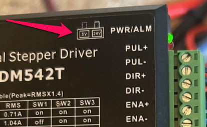
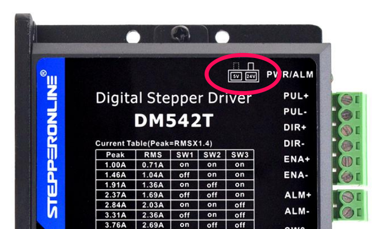
Some drivers have a signal voltage switch. These usually give a 5V and 24V option. You should use the 5V option for most controllers.
3.3V to 5V Level shifting
Some controllers will have this built in. The 6 Pack has a jumper option for 3.3V and 5V output option. You should use the 5V output with external drivers.
Note: Do not mix external with Trinamic (TMC) drivers when using 5V. TMC drivers send signals back to the ESP32 and will damage it with 5V
The 5V must have enough current to activate the LEDs inside the optoisolators. The current is generally in the range of 10 to 20mA, which is more than some level shifts can deliver . Some level shifters (like T.I. TXB type) use a pull up resistors for the 5V and this will not power an optocoupler.
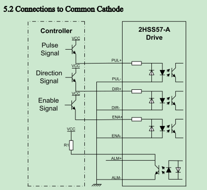
Here is a what a typical stepper driver looks like inside (ignore the controller side). Each signal connection basically goes top both sides of an LED. You see each connection is fully isolated from the rest of the stepper driver including the other signals connections. Therefore you must wire to both the + and - sides of each connection.
Here is a typical way to wire it with the (-) sides daisy chained.
You can also wire them with a common +5V on the (+) sides of the optos. The signal from the controller goes to the (-) side. The opto will turn on when the low side is 5V less than the 5V side, like ground. A simple NPN transistor will do this.
¶ Signals
These isolating input features can add a little lag time on the speed of detecting the step, direction and enable signals. FluidNC has several settings to compensate for this.
Many signals also have to be inverted. The isolation circuit flips the signal, so FluidNC may need to adjust for that.
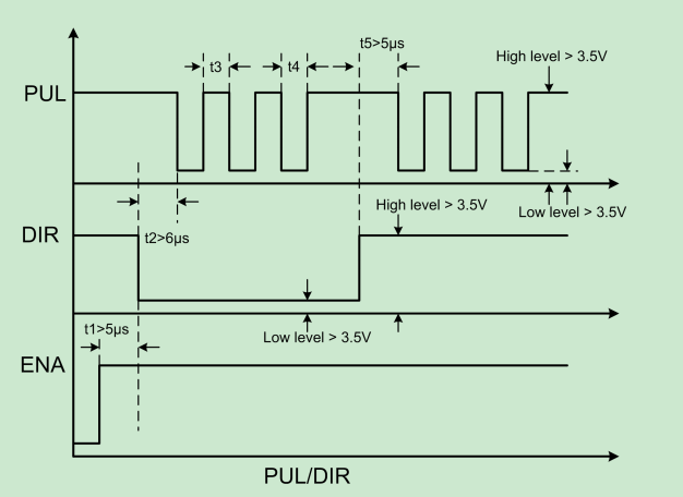
In the image below, you can see the pulse length requirements and required gaps between signals. The PUL (step signal) and DIR are inverted. The ENA is not, but you still might need to invert it because FluidNC considers it a disable signal. If the motors lock after you issue the FluidNC $MD (Motor/Disable) command and unlock (turn freely) after $ME (Motor/Enable), you have the enable backwards, and will have to either add or remove the :low attribute from the disable pin definition.
¶ Signal voltage
Most drivers are designed for 5V signals. Some are compatible with a range from 5V to 24V. Some have a voltage selector switch. Many drivers are compaible with a wide range of signal voltages.
It is important that you get this correct. If you get it wrong, you could damage the driver or the controller.
¶ Config
You should use the standard_stepper: motor type.
axes:
  x:
    # add axis details here
    motor0:
      standard_stepper:
        step_pin: is2o.0
        direction_pin: i2so.1
        disable_pin: i2so.2
¶ Settings
The following settings under the stepping: group can be used to control the pulse durations.
Here are the settings. The "t" numbers from the image above are indicated.
- pulse_us: (t4) This is the duration in microseconds of the step pulse.
- dir_delay_us: (t2) This is the delay between the end of the direction pulse and the beginning of the step pulse.
- disable_delay_us: (t1) This is the delay between the enable and the direction signal
Example: Stepping section
stepping:
  pulse_us: 2
  dir_delay_us: 1
  disable_delay_us: 0
¶ Adapters
There are a couple of adapters available to help with this. These both send the signals to the existing connectors.
6 Pack Adapter. This is just re-routes the 5V signals to the terminal blocks. It also allows the option of common 5V or common ground.
Note: Be very careful when wiring. If you short the outputs you could permanently damage the controller.

StepStick Adapter. This adapter does level shifting and re-routes the signals to the motor connector. It would be used on controllers that don't have 5V signals. It can be used on 3.3V or 5V controllers.

¶ Wiring
Each signal typically has a + and - connection. This allow you to wire them totally isolated from each other. The signals on the FluidNC side generally will not be isolated from each other and share a common ground.
The easiest way to wire that is to connect all the minus sides together and connect that to ground on the controller. Wire the plus sides to the signals. This is shown below.

You could also wire the + sides together and connect that to +5V on the controller side. The minus sides would connect to the signals on the controller side. This is shown below.

¶ Closed Loop Steppers and Servo Motors.
Closed loop stepper drivers and servo motors can be used as long as they have step and direction inputs.
Standard stepper motors simply step for each step signal and tend to be very accurate. Closed loop motors update a target position with each step signal and a PID postion control loop attempts maintain the position in sync with the target location.
Advantages
- Power: They can be more powerful without overheating. The power used is usually proportional to what is needed. Short bursts of high power can be used without causing overheating.
- Position Alarms: You can typically set a position error level error. For example: You could say 15 steps is the maximum position error. If this is exceeded, due to a blockage or other issue, they will shut sown and send an alarm signal. This can be tied to a FluidNC control input like the fault_pin to stop the job. A standard stepper motor typically does not give any indication of a problem.
Disadvantage
- Cost: They are typically about double the cost of an equivalent standard stepper motor/driver
- Accuracy: They can take a lot of tuning of the PID values to get the same accuaracy as a standard stepper motors. A little overshoot and oscillation is usually present.
- Complexity and reliability: The wiring is more complex. Some hobbyist level stuff especially the closed loop stepper motors with intregrated electronics are not very reliable and quit mid job for unknown reasons. If the program crashes you may not get an alarm signal.
- Power: The extra power can be a disadvantage too. When a closed loop stepper slams into something it will try very hard to keep going before finally shutting down. If an endstop is missed, a closed loop stepper can jam very hard into the mechanical limit, whereas an ordinary stepper might stall sooner and put less stress on the mechanical system.
Alarm Signal Usage
We have limited inputs, so you need typically to OR the alarm signals from multiple drivers togethers. If the signal comes from an opto of the driver these may float during normal operation and close to ground with an alarm. These will naturally OR. Otherwise you need an external OR circuit.
¶ Troubleshooting
As far as FluidNC is concerned, external drivers are the simplest stepper motors. It is very unlikely there is a firmware problem. Problems almost always have something to do with your driver, the wiring or the stepping config.
- Erratic or missed steps
- This is often due to the step timing. These drivers often need longer pulse lengths to be reliably detected. Try lengthening the pulses.
- Check the signal voltage
- Motors don't lock
- Use this flowchart to debug the problem.
- Many drivers will lock by default if the enable signal is not used. This means you might need to add the
:lowattribute to your pin definition.
¶ Optocoupler Analysis
Optocouplers are often misunderstood. They do not work like most other common circuit elements that are sensitive primarily to voltage differences. Optocouplers work by passing current through an internal LED whose light shines on an internal phototransistor. The phototransistor then conducts current depending on how much light is falling on it.
The optocoupler LED always has a resistor in series with it to limit the current. That resistor is usually inside the external driver box. Its value is often in the range of 220 to 470 ohms, but there is no real standard for what the value should be.
The amount of current that goes through the LED can be calculated as Iled = (Vin - Vf) / R, where Iled is the current through the LED, Vin is the input voltage across the combination of the resistor and the optocoupler, Vf is the "forward voltage" of the LED - usually about 1.1V - and R is the external resistor value. If, for example, the resistor value is 220 ohms, then with Vin = 3.3V, Iled is (3.3 - 1.1) / 220 = 10 mA. At Vin = 5V, a similar calculation gives Iled = 17mA. But that is only the input side of the story. The phototransistor and its external load resistor must also be considered.
Optocouplers are specified by Current Transfer Ratio (CTR), which is the ratio between the LED current and the current through the phototransistor when it is illuminated. The CTR value typically ranges from 50% (phototransitor current is half of LED current) to 200% (phototransistor current is twice the LED current). That spec is not very precise. It changes with the LED current, the temperature, the age of the device, the load resistance in the circuit on the phototransistor end, the part number of the optocoupler, and from unit to unit.
If we assume a CTR at the low end of the usual range, say 50%, if Iled is 10 mA, then the phototransistor current will be 5mA. That would be enough to drive a 1000 ohm load resistor to 5V, more than enough to create a logic 1 state on the downstream circuitry. The load resistors in external drivers are often much more than 1000 ohms - say perhaps 5K - so 1mA of phototransistor current would be plenty.
But the problem is usually not turn-on, but rather turn-off. When you stop illuminating a phototransistor, it doesn't stop conducting current immediately. It can take many milliseconds before the light-induced charge carriers in the phototransitor dissipate and let the phototransistor stop conducting. The turn-off time can be decreased by using very small load resistors, but that is not typically done in external drivers.
¶ Video Script (for possible future video)
These days external motor driver modules are very popular. They can deliver a lot more power than plug in stepstick style module or on board drivers. They also have closed loop versions which adds additional appeal for some people.
FluidNC can control most of them. The only thing the motor drivers need to have is the ability to use step and direction signal inputs. Most also have an enable signal input.
The inputs are typically optical isolators. This helps prevent noise from the motors getting back to the motion controller. The signal from the controller lights an LED to activate the input. Your controller must be able to power this LED.
The opto isolators can cause a lot of issues for people leading them to think something is wrong with the controller or FluidNC. This this will help you follow a logical procedure to figure out the problem.
Most controllers output a 3.3V or 5V signal. Make sure your voltage is compatible with the optos on the motor driver. Most motor drivers are, but some have a switch to select between 5V and a higher voltage like 24V. Be sure to check for that switch and set the voltage correctly. The opto's LEDs require a little current this is typically around 10mA. Some level shifters use pullup resistors for the + voltage. These cannot deliver enough current. Don't use level shifters unless you are sure they can power the LED.
Here is what the input circuit on a typical driver looks like. Each LED requires a positive voltage and a negative voltage (typically ground). Most people wire the negative side to the ground on the controller and connect the output signals from the controller to the plus side.
+
You can also wire the plus side to a constant voltage and connect the negative side to your output signals. This is usually done when your output signals switch to ground and cannot drive any current in the open state like a NPN transistor. Some voltage level shifters work this way.
The motor datasheet should also tell you the active states (high/low) of the inputs and the pulse timing. Both of these can be set in the FluidNC config file, so it should not impact your wiring choices.
¶ Power
Ideally you should use a separate power supply from the controller power supply. Using a common supply will defeat the noise isolation of the optos.
I am going to use a basic stepper motor setup for this video. Closed loop stepper and servo motors should be similar but have some extra wiring for the encoders.
¶ Buying tips.
Make sure you can get the motor driver datasheet before you buy. Many aliexpresss and Amazon sellers don't have them. That is a red flag. Many drivers are cheap copies. They may even use the same name and part number of reputable places like stepper online and leadshine. Sometimes off-brand drivers have vastly inferior circuitry that is totally unlike what is inside reputable brands with a similar part number.
Good feature to looks for are a good range of
¶ Stepper Motor Driver setup
Follow the order of these instructions to help test things as you go. Do one at at time, so if you learn anything as you go, you can apply it to the others
Wire the motor: Before wiring the motor to the driver make sure no wires are touching each other. Make sure you can turn the motor by hand. If you cannot, try putting a pulley or something on the shaft to get a little more leverage. Checking to see when the motor can turn or is locked in place when enabled is very helpful in checking your setup.
Determine which pairs of wires belong to the motor coils. Your datasheet should tell you. The coils are often designated as A and B. If the wire colors are black, green, red and blue, black(A+) and green(A-) are a pair and red(B+) and blue(B- ) are a pair. You don't really need to worry about making sure which pair is A or B, and which wire of the pair is + or -. This will only affect the motor direction. We can correct direction in the firmware. You just need to make sure each coil goes to a plus and minus. With this said, it is nice to be correct and consistent if you need to swap drives or rewire in the future.
Now test that you can still rotate the motor. It should still rotate freely when the power is off.
¶ Set the current and microstepping
This is usually done via some DIP switches. The motor datasheet should tell you the max current. Most can safely run quite hot, but you might want to run a little cooler, especially if you have 3D printed parts in contact with the motor. A good starting point might be around 80% of the max on the datasheet.
¶ Power On Test
Connect the power. Do not connect anything to the controller. For most drivers, the enable signal is optional and will enable if not used. Turn on the power supply. You might hear a thump as the motor locks onto the first full step position. It should be difficult or impossible to turn the motor by hand. If that is not the case, check your datasheet to make sure they enable by default. If they do recheck your wiring. If they don't then move on to the next step.
¶ Controller Testing (before connecting motor)
Make sure you do not have any errors in your startup messages. Many controllers like the 6x, Corgi and Doberman have LEDs. These will show you the status of the output signals. The LEDs will light when the output off the pin is high. The LEDs on most controller are wired directly to the signal. Most LEDs require at least 2.5V to light, so if you see them light, you can assume the full voltage is going out.
You can send some move commands G91 G0 X100 will be a positive move of 100 on Xand G91 G0 X-100 will be a negative move of 100.
- Enable/Disable LED The best way to test this is by sending
$Motor/Enable (or $ME)and$Motor/Disable (or $MD)This will toggle the state of the LED. Note: You can target one axes by adding the axis letter like$ME=X - Dir LED This will be on for one direstion and off for the opposite direction. It will stay in the last state. Try moving both directions. The LED should change from on to off.
- Step LED This will turn on for a few microseconds for each step. That is a really small amount of time, so you may only be able to see it a higher speed. Higher speeds shortens the off time between steps. Longer distance moves in G0 mode will give it time to reach higher speeds. It will look quite dim at best. If you still cannot see it try changing the active state (:high/:low) of the step pin just for this test.
If you cannot get the LEDs to behave you need to figure that out before connecting the motor driver.
If you really think that a pin like i2so.2, for example, is dead, try swapping the pin assignment to a function like coolant/flood_pin. Check your startup messages for errors, then toggle the state with M8 and M9.
coolant:
  flood_pin: i2so.2
¶ Wiring
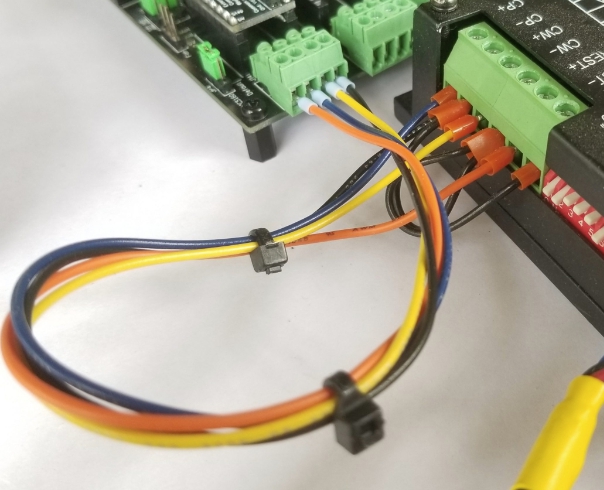
The ideal way to wire the signals to the motor is to use a common ground. The black wire goes from the controller ground to each of the (-) sides of the 3 signals. The disable, step and direction signals from the controller go to the (+) sides on the motor driver.
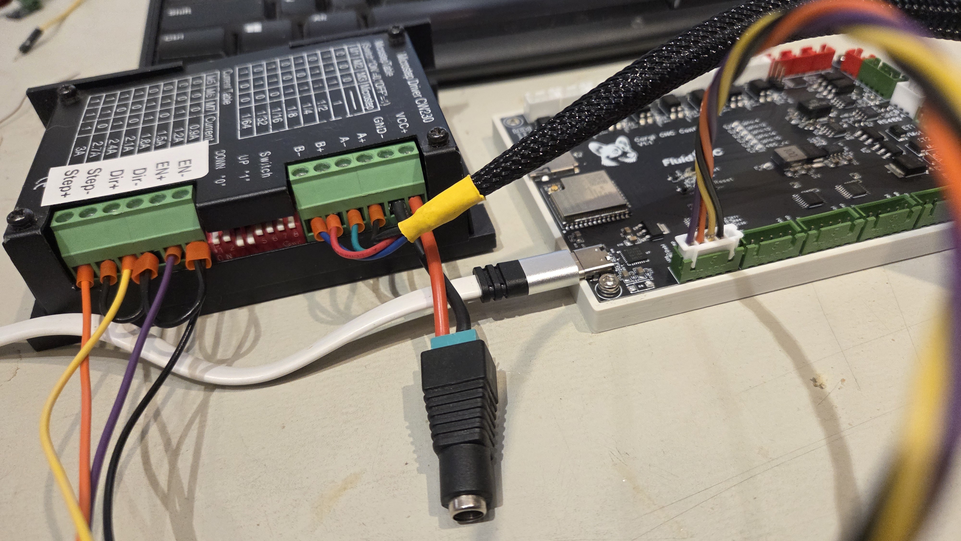
Here is how the Corgi controller would be wired. The black wire is the ground and ius daisy chained on the driver side. The orange, yellow and purple wires are the step, dir and enable wires. The 5V pin on the corgi is not used.
¶ Testing
¶ Enable/Disable
With everything connected and powered on send $ME. The motor should be locked. Send $MD. The motor should be unlocked.
- If the it is backwards, then change the active state of the
disable_pin:in the config file, restart the controller and test again. - If it is locked for both $ME and $MD, then the signal is probably not reaching the motor driver. Is the LED changing states?
- If it is not locked for either $ME or $MD then something is not right. Is the LED changing states?
Do not move on to the next test until the disable is working.
¶ Testing motion
For initial motion testing you need to start at a slow speed, because if you try to go faster than the motors can handle, they will stall or move erratically. To set the speed to a slow rate, first send G1 F1000. That sets the rate to 1000 mm per minute, which most motors can handle for most reasonable config settings of steps_per_mm and microsteps.
Send G91 G1 X10. The motor should move in a forward direction. Send G91 G1 X-10. The motor should move in the opposite direction. Note that, unlike the tests above, these commands use G1 not G0. G0 is fine for testing without motors, but with motors, it could easily pulse to rapidly for the motors to keep up.
- If the motor does not move att all, you have a problem with the step signal. Is the LED changing?
- If the motor moves in the smee direction for both commands, you have a problem with the direction signal. Is the LED changing states?
- If the motor moves both way, but backwards from what you want then change the active state of the
direction_pin:in the config file, restart the controller and test again.