¶ The Doberman CNC Controller

¶ Overview
The Dobernam is a CNC controller for use with external stepper motor drivers. It is very similar to the Corgi controller, except it uses a ESP32-S3 CPU which has more I/O and a native USB connector.
It also has a CNC I/O module socket in the center of the controller. This can be used to add extra inputs, outputs, MOSFETs, etc. You can also design your own if you have a special requirement.
¶ Where to buy it
¶ Features
- ESP32-S3-WROOM-1-N8R8 (8M FLASH, 8M PSRAM)
- (8) Stepper motor connectors
- (10) Input inputs
- (4) 5V outputs
- 0-10V Spindle interface
- Isolated RS485 Spindle interface
- (2) MOSFET outputs
- Standard CNC I/O module socket that can add inputs, outputs, MOSFETs, etc.
- RJ12 standard UART interface for pendants and display.
- Micro SD card socket
- USB C primary USB/UART interface
- Secondardary USB C connector that can be used as a UART. It also support the future use as a host for devices like joysticks and jog controllers.
¶ Versions
- The current version is V1.0
¶ Getting Started
The controller ships with a version of FluidNC that was current when the controller was built. You should upgrade the firmware using the web installer.
- Do not install your config file yet.
- Do not connect any external devices yet.
- Connect the antenna. You should only operate when the antenna is connected. A missing antenna can cause the ESP32 chip to overheat.
- Connect main power. Be sure the polarity is correct before you turn on the power.
- Turn on the main power and confirm that the 5v LED (green, near the center of the PCB) is lit.
- Connect a USB-C cable between your computer and the controller. Use the USB connector labeled USB UART. Check to see that your computer has added a serial port.
- Go to the web installer. Connect to your controller.
- Click the button to open the terminal. Enter the command $localfs/run=test.nc. This should sequencially blink all of the I/O test LEDs on the controller.
- Do an upgrade (not full installation). Be sure to select the ESP32-S3 processor type.
- You may want to connect to your wifi at this time.
- Now create and load a config file for your machine.
- Power down and connect all your devices. It might be helpful to connect just a few at a time and test as you go.
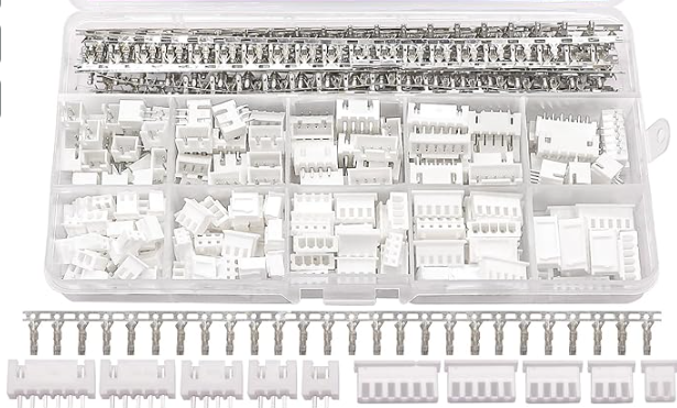
¶ Mating Connectors
The mating connectors are female JST XH (2.5mm) 2, 3 and 5 pin connectors. They are not provided. A complete kit is easily found on Amazon (~$10), AliExpress or other places. Be sure to get a high quality crimping tool, if you do not have one. Search for "JST XH connector kit"
¶ Power
The controller should be powered by 12V. Your power supply should be able to provide about 1A for the basic controller functions plus whatever current is attached to the MOSFET terminal. The terminal block is rated for 10A. It should be connected to the "Vin" pins on the green terminal block. Double check the polarity before powering on, but there is reverse polarity protection.
A green LED will light in the center of the conntroller when power is properly applied. Depending on the state of the controller other LEDs may also light or blink.
You cannot power the controller with either USB connector. You must have primary power connected for anything to work including USB.
¶ Processor Type
The Doberman uses an Espressif ESP32-S3-WROOM-1U-N8R8. Be sure to select this the ESP32-S3 processor when installing or upgrading firmware.
¶ Antenna
The antenna connector is an IPEX connector type. It ships with a basic one like this. You can easily find larger or more directional ones on Amazon or AliExpress. You should always have an antenna connected when using the Wifi or Bluetooth modes.

¶ Primary USB
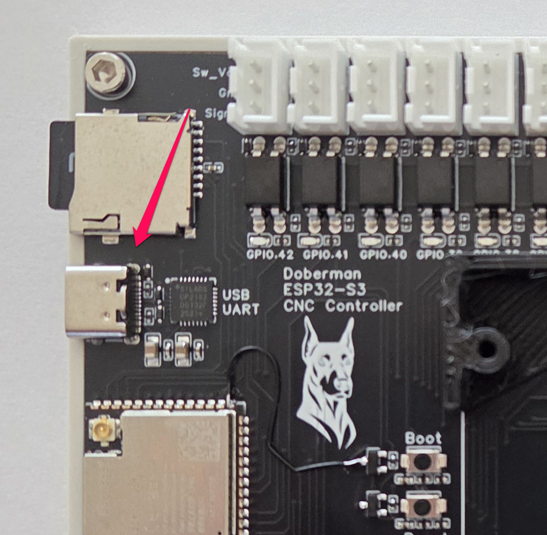
The primary USB, labeled USB UART, is a Silcon Labs CP2102 USB/Serial chip. Most computers ship with a driver for that. You can get the latest driver from them if it is not working.
The USB connection has nothing to do with the firmware or the ESP32. If you are not getting a connection, it is not a firmware issue. It is most likely a driver or cable issue.
You must have primary power for the USB to work.
¶ Secondary USB
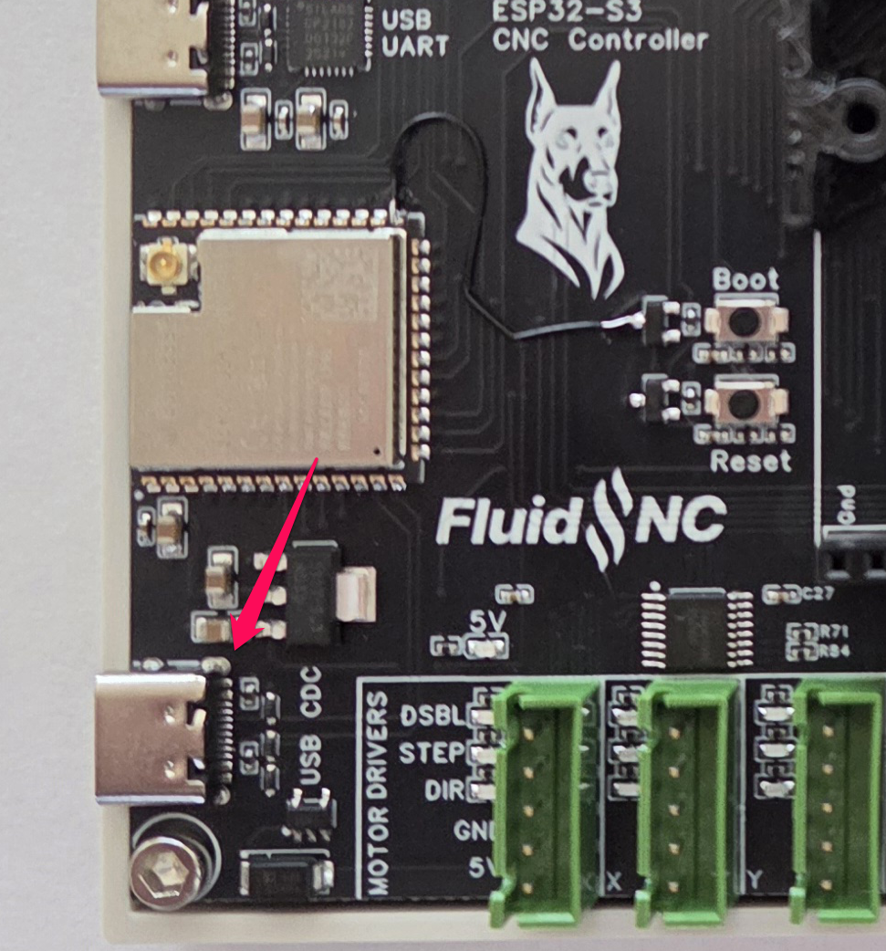
This feature is experimental at this time
The other USB connector, labeled USB CDC, connects directly to the ESP32. By default this native USB will be a CDC (communication device class) USB/Serial UART. Most computers will already have a driver for this.
This USB can also work in host mode, where it can communicate and power devices like keyboards, joysticks, wire ethernet and jog controllers.
At this time FluidNC has no support for any devices in host mode. The connector was tested using simple example sketches of host mode. There is no guarantee that FluidNC will ever support this. This was just an attempt to future proof the controller and work as a development platform.
¶ Motor Driver Outputs
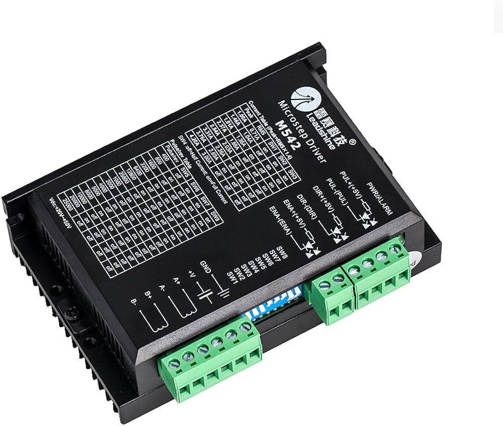
The controller is designed for use with external stepper driver modules that accept 5V step, direction, and enable signals. They all use i2so pins, so you need to use I2S_STATIC (recommended) or I2S_STREAM in the stepping section of your config file.
stepping:
  engine: I2S_static
  idle_ms: 255
  pulse_us: 4
  dir_delay_us: 4
  disable_delay_us: 0
  segments: 6
Each connector has a disable signal, step signal, direction signal, gnd and 5V. You can either use gnd or 5V as the common pin.
Any motor output can be used for any axis or motor number. They are labeled XYZACBUV, just for reference.
Here are the pins for each motors.
# motor X
      standard_stepper:
        step_pin: I2SO.0
        direction_pin: I2SO.1
        disable_pin: I2SO.2

# motor Y
      standard_stepper:
        step_pin: I2SO.3
        direction_pin: I2SO.4
        disable_pin: I2SO.5

# motor Z
      standard_stepper:
        step_pin: I2SO.6
        direction_pin: I2SO.7
        disable_pin: I2SO.8

# motor A
      standard_stepper:
        step_pin: I2SO.9
        direction_pin: I2SO.10
        disable_pin: I2SO.11

# motor B
      standard_stepper:
        step_pin: I2SO.12
        direction_pin: I2SO.13
        disable_pin: I2SO.14

# motor C
      standard_stepper:
        step_pin: I2SO.15
        direction_pin: I2SO.16
        disable_pin: I2SO.17

# motor U
      standard_stepper:
        step_pin: I2SO.18
        direction_pin: I2SO.19
        disable_pin: I2SO.20

# motor V
      standard_stepper:
        step_pin: I2SO.21
        direction_pin: I2SO.22
        disable_pin: I2SO.23
¶ Motor Driver Wiring
Most external stepper drivers typically have 6 connections. These are 3 pairs (+ and -) for step, dir and enable. Step is often labeled pulse or pul. Each pair is for an optoisolator.
You can connect the signal to either the + or - side of the opto. The other side side of the opto would go the the gnd or +5v pins. You do not need to wire every motor signal with the same pattern. Do whatever is appropiate for each motor diver signal.
Most people wire ground to all the (-) pins to bnd and the signal pins to the (+) side. Any inversions needed can be done in firmware with the :high and :low pin configuration attributes.
Be careful not to short or overload these pins. You will destroy the I2SO chips.
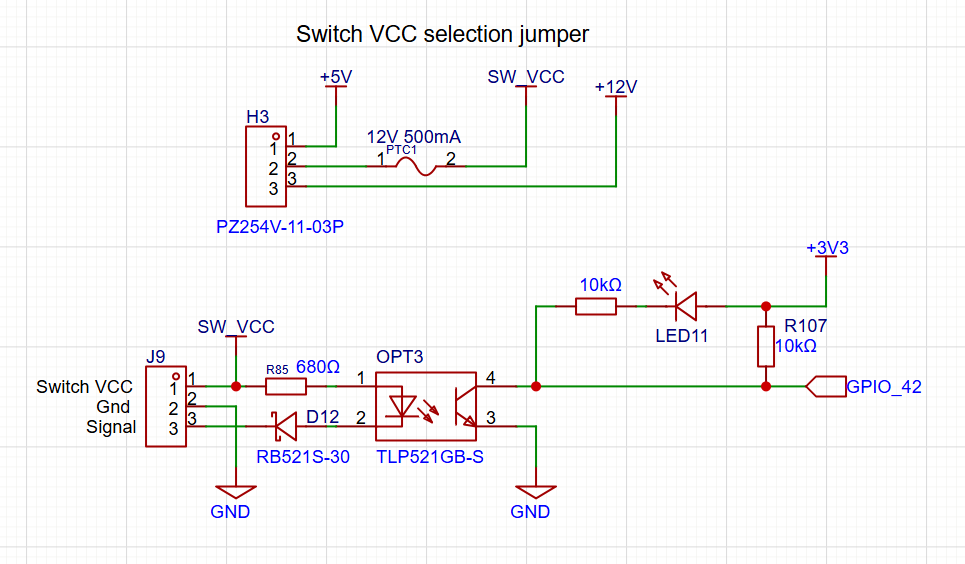
¶ Inputs
The input connectors are the 3 pin white connectors along the top edge. Each connector has a Switch Vcc, Gnd and signal pin. The switch Vcc is used to turn on the opto LED and can be used for switches that require power. Switch Vcc is selectable between Vin and 5v via a jumper near the right most input connector. You must use a jumper to select one of these voltages.
The jumper affects the switch Vcc for all input connectors. You cannot have a mix of voltages across the connectors. You can use external power for switches if a switch needs a special voltage. Just make sure to create a common ground with the controller's power supply.
All inputs activate by connecting the signal to ground. You can use N.O. and N.C switch as long as one position closes to ground and will conduct enough current to light the opto LED on the controller. There is a reverse voltage protection diode for switches that have pullups in the inactive state.
You can use electronic switches like proximity or inductive switches as long as the output signal switches to ground when active (typically called NPN). All of the inputs have external pullup resistors. You do not need the :pu attribute
For N.O. switches you need the :low attribute on all inputs. N.C. switches are active high. You can add the :high attribute, but it is not needed because that is default in FluidNC.
Each input has an LED to show when the circuit is low state (signal connected to ground). This can be helpful to diagnose wiring issues.
Be careful with switches that already have a 3 pin JST XH connector. The pinout is likely to be wrong. Double check that the switch pinout matches the Doberman pinout.
Be careful not to short Switch Vcc to ground. There is a auto reset 500mA PTC fuse on the Vcc to protect it from permanent damage in the event of a short.
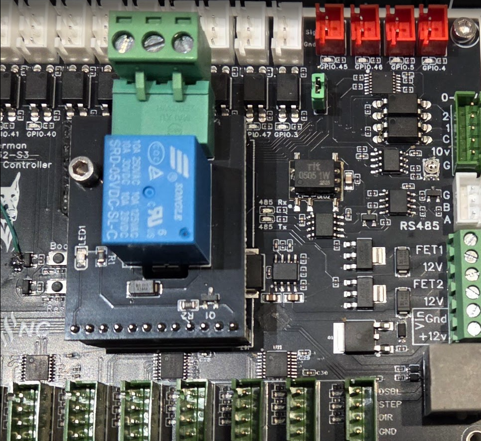
¶ Outputs
You can use up to (4) output signals at one time. (2) of the output signals are connected to both a 5V output and a MOSFET. Therefore, you cannot use all (6) output circuits completely independently. There are status LEDs for each output gpio pin. They are located near the associated 5V output connector.
- gpio.4 (connected to a 5V output and a MOSFET)
- gpio.5 (connected to a 5V output and a MOSFET)
- gpio.45 (connected to a 5V output)
- gpio.46 (connected to a 5V output)
¶ 5V outputs
The 5V outputs are on the (4) 2 pin red connectors. They can do digital or PWM. They are driven by a 74AHCT125 chip. They can do 20mA each, but only 50mA in total for all 4 outputs.
The outputs are from left to right.
- gpio.4 (note this will also activate MOSFET1)
- gpio.5 (note this will also activate MOSFET2)
- gpio.46
- gpio.45
¶ MOSFETs
The (2) NPN MOSFETs are rated for 3A continuous and 5A peak. There are flyback diodes connected to VMot to make them safe for use with inductive loads, such as relays, small motors and solenoids.
The VMot terminals are always connected to 12V. Terminals labeled with the io pin numbers switch to ground when the io pins are active. If you need to operate devices with other voltages than 12v, you can use a separate DC power supply as long as it shares a common ground with the controller.
- FET1 gpio.4 (this will also activate one of the 5V outputs)
- FET2 gpio.5 (this will also activate one of the 5V outputs)
¶ Using Relays with the MOSFETs
You can attach relays directly to the MOSFET terminal block. The coil voltage of the relay must be 12V unless you are supplying an external voltage. If the coil has + and - labeled for the coil, be sure to get that connected to the controller correctly.
¶ 0-10V Spindle
This uses an op-amp and a low pass filter to create an analog voltage. It can be adjusted with a trim pot for a max voltage of 5V to 10V. Measure and adjust the voltage before connecting to your spindle speed controller. A good way to do this is to send the gcode for max spindle speed like (M3 S24000 or whatever your max is) and then adjust the pot until you get the desired max voltage. It is best to set the max voltage before connecting to your VFD.
Most VFDs have a 10V output. Do not connect this to the controller. Connect the 10V signal to the 10V input on the VFD.
The forward and reverse signals use opto to connect to a common ground. This ground needs to come from the VFD.

10V:
  forward_pin: gpio.7
  reverse_pin: gpio.8
  pwm_hz: 5000
  output_pin: gpio.6
  enable_pin: NO_PIN
  direction_pin: NO_PIN
  disable_with_s0: false
  s0_with_disable: true
  spinup_ms: 0
  spindown_ms: 0
  tool_num: 0
  speed_map: 0=0.000% 1000=0.000% 24000=100.000%
  off_on_alarm: false
¶ RS485
The RS485 circuit is fully isolated. It also has automatic direction control, so it does not use an rts_pin
There are LEDs to show and help debug communications issues.
- TX LED (labeled "485 Tx") You should see the TX blink a couple times per second. If you do not, something is wrong in your setup on the CNC controller side.
- Rx LED (labeled "485 Rx") The Rx should blink at the same rate (immediately after) as the Tx LED when communicating with the VFD. If the Rx LED stays on, try swapping the wires on the VFD side. If it does not light at all, there is probably a setup or other problem on the VFD side. Note: When no RS485 wires are connected the state of the LED is meaningless. Ignore that LED when not using RS485.
Note: The circuit is a UART to RS485 converter. The LEDs represent the state of UART side IO.
RS485 is a lot more complicated to setup than other types of spindles. It requires a lot of setup on the VFD side and good wiring. If you are having trouble, you should consider using the 0-10V method to control the spindle. It is very hard for us to support RS485 remotely.
¶ RS485 Wiring
You should use 22-24AWG wires that are tightly twisted with at least 1 twist per inch. You can also use a twisted pair from some CAT5/6 cable.
You generally do not need a shield over the wires. If you do use a shield it should be grounded at the Doberman side. Do not connect the ground on the Doberman side to the VFD. This will defeat the isolation feature of the circuit.
VFDs are very noisy devices, especially the cheap ones. Some people have persistent communication problems that cannot be fixed.
¶ RS485 Config File
Here is a typical RS485 config file section. You must also setup the VFD and get the wiring correct. For general information about VFD setup see the spindle wiki page.
For the my Huanyang, I connect the terminal labeled RS485 A on the controller to RS+ on the VFD and RS485 B on the controller to RS- on the VFD. Most people should not connect the ground terminal.
# Begin Huanyang
uart1:
  txd_pin: gpio.12
  rxd_pin: gpio.11
  baud: 9600
  mode: 8N1

Huanyang:
  uart_num: 1
  modbus_id: 1
  tool_num: 0
  speed_map: 0=0% 0=25% 6000=25% 24000=100%
  off_on_alarm: false
¶ Other Spindles
Use the 5V outputs to control PWM spindles and lasers. You can also use the 5V outputs for enables and direction signals.
¶ SD Card
The micro SD card uses SPI and must be configured like this.
spi:
  miso_pin: gpio.2
  mosi_pin: gpio.1
  sck_pin: gpio.21

sdcard:
  card_detect_pin: NO_PIN
  cs_pin: gpio.9
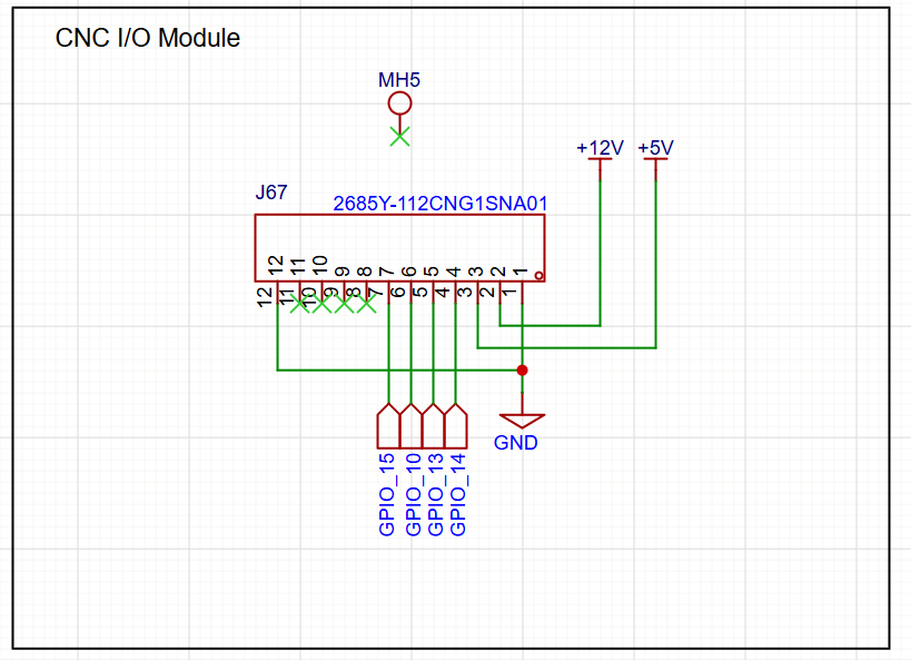
¶ CNC I/O Module Socket
The controller also has a standard CNC I/O module socket in the center of the controller. This socket can be used with any CNC I/O module.
You should use an 11mm spacer to support the module (not included).
¶ Expansion Port
The expansion port is a standard RJ12 connector compatible with the Airedale I/O expander and most pendands.
# Begin expansion port uart and channel setup
uart2:
  txd_pin: gpio.0
  rxd_pin: gpio.35
  baud: 1000000
  mode: 8N1

uart_channel2:
  report_interval_ms: 75
  uart_num: 2
# End expansion port set up.
¶ Example Config File
board: Dobermann S3
name: Dobermann Example

stepping:
  engine: I2S_STATIC
  idle_ms: 254
  pulse_us: 4
  dir_delay_us: 1
  disable_delay_us: 0

i2so:
  bck_pin: gpio.16
  data_pin: gpio.17
  ws_pin: gpio.18

# Begin expansion port uart and channel setup
# uart2:
  # txd_pin: gpio.0
  # rxd_pin: gpio.35
  # baud: 1000000
  # mode: 8N1

# uart_channel2:
  # report_interval_ms: 75
  # uart_num: 2
# End expansion port set up.

axes:
  shared_stepper_disable_pin: NO_PIN
  x:
    steps_per_mm: 800.000
    max_rate_mm_per_min: 5000.000
    acceleration_mm_per_sec2: 100.000
    max_travel_mm: 300.000
    soft_limits: false
    homing:
      cycle: 2
      positive_direction: false
      mpos_mm: 150.000
      feed_mm_per_min: 100.000
      seek_mm_per_min: 200.000
      settle_ms: 500
      seek_scaler: 1.100
      feed_scaler: 1.100

    motor0:
      limit_neg_pin: gpio.42:low:pu
      limit_pos_pin: NO_PIN
      limit_all_pin: NO_PIN
      hard_limits: false
      pulloff_mm: 1.000
      standard_stepper:
        step_pin: I2SO.0
        direction_pin: I2SO.1
        disable_pin: I2SO.2

    motor1:
      limit_neg_pin: gpio.41:low:pu
      limit_pos_pin: NO_PIN
      limit_all_pin: NO_PIN
      hard_limits: false
      pulloff_mm: 1.000
      standard_stepper:
        step_pin: I2SO.3
        direction_pin: I2SO.4
        disable_pin: I2SO.5

  y:
    steps_per_mm: 800.000
    max_rate_mm_per_min: 5000.000
    acceleration_mm_per_sec2: 100.000
    max_travel_mm: 300.000
    soft_limits: false
    homing:
      cycle: 2
      positive_direction: false
      mpos_mm: 150.000
      feed_mm_per_min: 100.000
      seek_mm_per_min: 200.000
      settle_ms: 500
      seek_scaler: 1.100
      feed_scaler: 1.100

    motor0:
      limit_neg_pin: gpio.40:low:pu
      limit_pos_pin: NO_PIN
      limit_all_pin: NO_PIN
      hard_limits: false
      pulloff_mm: 1.000
      standard_stepper:
        step_pin: I2SO.6
        direction_pin: I2SO.7
        disable_pin: I2SO.8

    motor1:
      limit_neg_pin: gpio.39:low:pu
      limit_pos_pin: NO_PIN
      limit_all_pin: NO_PIN
      hard_limits: false
      pulloff_mm: 1.000
      standard_stepper:
        step_pin: I2SO.9
        direction_pin: I2SO.10
        disable_pin: I2SO.11


  z:
    steps_per_mm: 800.000
    max_rate_mm_per_min: 5000.000
    acceleration_mm_per_sec2: 100.000
    max_travel_mm: 300.000
    soft_limits: false
    homing:
      cycle: 2
      positive_direction: true
      mpos_mm: 150.000
      feed_mm_per_min: 100.000
      seek_mm_per_min: 200.000
      settle_ms: 500
      seek_scaler: 1.100
      feed_scaler: 1.100

    motor0:
      limit_neg_pin: NO_PIN
      limit_pos_pin: NO_PIN
      limit_all_pin: gpio.38:low:pu
      hard_limits: false
      pulloff_mm: 1.000
      standard_stepper:
        step_pin: I2SO.12
        direction_pin: I2SO.13
        disable_pin: I2SO.14

    motor1:
      limit_neg_pin: NO_PIN
      limit_pos_pin: NO_PIN
      limit_all_pin: gpio.37:low:pu
      hard_limits: false
      pulloff_mm: 1.000
      standard_stepper:
        step_pin: I2SO.15
        direction_pin: I2SO.16
        disable_pin: I2SO.17

  a:
    steps_per_mm: 800.000
    max_rate_mm_per_min: 5000.000
    acceleration_mm_per_sec2: 100.000
    max_travel_mm: 300.000
    soft_limits: false
    homing:
      cycle: 2
      positive_direction: false
      mpos_mm: 150.000
      feed_mm_per_min: 100.000
      seek_mm_per_min: 200.000
      settle_ms: 500
      seek_scaler: 1.100
      feed_scaler: 1.100

    motor0:
      limit_neg_pin: gpio.36:low:pu
      limit_pos_pin: NO_PIN
      limit_all_pin: NO_PIN
      hard_limits: false
      pulloff_mm: 1.000
      standard_stepper:
        step_pin: I2SO.18
        direction_pin: I2SO.19
        disable_pin: I2SO.20

    motor1:
      limit_neg_pin: gpio.48:low:pu
      limit_pos_pin: NO_PIN
      limit_all_pin: NO_PIN
      hard_limits: false
      pulloff_mm: 1.000
      standard_stepper:
        step_pin: I2SO.21
        direction_pin: I2SO.22
        disable_pin: I2SO.23

spi:
  miso_pin: gpio.2
  mosi_pin: gpio.1
  sck_pin: gpio.21

sdcard:
  card_detect_pin: NO_PIN
  cs_pin: gpio.9

probe:
  pin: gpio.47:low
  toolsetter_pin: gpio.3:low
  check_mode_start: true
  hard_stop: false

coolant:
  flood_pin: gpio.45
  mist_pin: gpio.46

user_outputs:
  digital0_pin: gpio.4
  digital1_pin: gpio.5

# 10V:
  # forward_pin: gpio.7
  # reverse_pin: gpio.8
  # pwm_hz: 5000
  # output_pin: gpio.6
  # enable_pin: NO_PIN
  # direction_pin: NO_PIN
  # disable_with_s0: false
  # s0_with_disable: true
  # spinup_ms: 0
  # spindown_ms: 0
  # tool_num: 0
  # speed_map: 0=0.000% 1000=0.000% 24000=100.000%
  # off_on_alarm: false


## Start RS485 Spindle
# uart1:
  # txd_pin: gpio.12
  # rxd_pin: gpio.11
  # rts_pin: NO_PIN
  # baud: 9600
  # mode: 8N1

# ModbusVFD:
  # uart_num: 1
  # modbus_id: 1
  # poll_ms: 1000
  # model: Huanyang
  # debug: 0
  # tool_num: 0
  # cw_cmd: 03 01 01 > echo
  # ccw_cmd: 03 01 11 > echo
  # off_cmd: 03 01 08 > echo
  # set_rpm_cmd: 05 02 rpm*100/60 > echo
  # get_min_rpm_cmd: 01 03 0b 00 00 > 01 03 0B minRPM*60/100
  # get_max_rpm_cmd: 01 03 05 00 00 > 01 03 05 maxRPM*60/100
  # get_rpm_cmd: 04 03 01 00 00 > 04 03 01 rpm*60/100

## End RS485

# relay:
  # direction_pin: NO_PIN
  # output_pin: gpio.4
  # enable_pin: NO_PIN
  # disable_with_s0: false
  # s0_with_disable: true
  # spinup_ms: 0
  # spindown_ms: 0
  # tool_num: 0
  # speed_map: 0=0.000% 0=100.000% 1=100.000%
  # off_on_alarm: false

start:
  must_home: false
¶ Simple I/O Test
You can use this macro to do some simple I/O tests. Load the example config file above and set $config/filename to that file. Load the file below into the local file system as test.nc Run the file with $localfs/run=test.nc
It should...
- Sequencially blink the LEDs below the the (4) red 2 pin connectors along the top of the controller.
- Blink the LEDs for all the motor connector and leave the DSBL LEDs on.
M62 P0 ; test IO4
G4P1
M63P0  ; test IO5
M62P1
G4P1
M63P1
M7    ; test IO45
G4P0.5
M8    ; test io46
G4 P0.5
M9
; test steppers
G0 X10 y10 z10 a10
G0 X0 y0 z0 a0
G0 X10 y10 z10 a10
G0 X0 y0 z0 a0
G0 X10 y10 z10 a10
G4P2
$motor/disable
¶ Source Files
¶ Factory Firmware
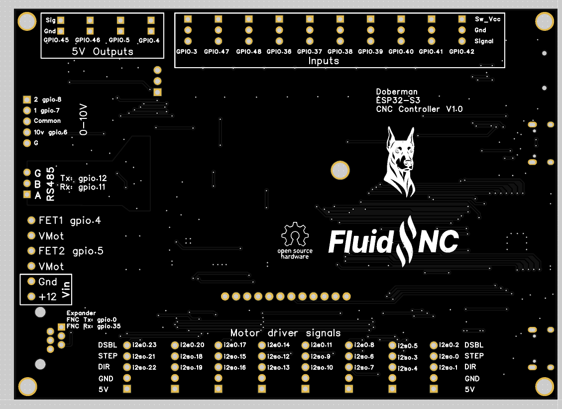
¶ Pinout Diagram
The pinout is on the back of the controller