¶ 4x CNC Controller (Integrated ESP32 and TMC2209)
Incomplete - This is a work in progress
¶ Overview
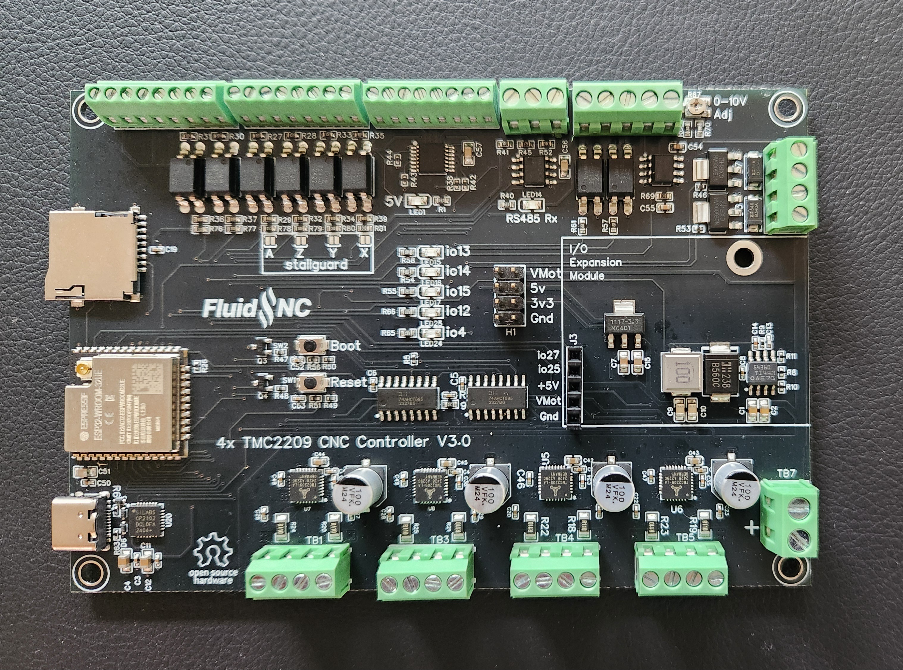
This is a 4 Axis CNC controller with (4) built in TMC2209 stepper motor drivers and a built in ESP32 module. The firmware has full control of the motor drivers via UART to set the microstepping, current and other features. You can use Stallguard sensorless endstops by directing that signal to limit switch inputs via solder jumpers.
It was intended to look very much like the 6x controller. The TMC2209 drivers do require more I/O than external drivers, so there are fewer inputs.
¶ Features
-
(4) TMC2209 Stepper Drivers in UART Mode
-
Can use stallguard for sensorless end stops
-
(6) inputs
-
(4) 5V Outputs
-
(2) 3A MOSFET Outputs
-
(1) 0-10V Spindle output
-
(1) RS485 interface for spindle VFDs
-
(1) I/O Expansion Module Socket
-
SD Card socket.
-
USB-C
¶ Where to buy
Coming soon
¶ Getting Started
The controller ships with a version of FluidNC that was current when the controller was built. You should do an upgrade to get the current version.
- Do not install your config file yet.
- Do not connect any external devices yet.
- Do not connect the USB yet. It will not work yet anyway.
- Connect the antenna. You should only operate when the antenna is connected. A missing antenna can cause the device to overheat.
- Connect main power. Be sure the polarity is correct before you turn on the power.
- Turn on the main power and confirm that the 5v LED is lit.
- Connect a USB-C cable between your computer and the controller. Check to see that your computer has added a serial port. See below if you have a problem.
- Go to the web installer. Connect to your controller and do an upgrade.
- You may want to connect to your wifi at this time.
- Now create and load a config file for your maqchine.
- Power down and connect all your devices. It might be helpful to connect just a few at a time and test as you go
¶ Install latest firmware
Use the WebUI or release files to install the latest firmware. It is probably best to do a full install rather than just an upgrade
¶ Create a config file
Create and upload a config file for your machine.
¶ Power Supply Requirements
The TMC2209 stepper drivers primarily determine the voltage and current specifications of the power supply. They are rated at 2A each and have a max voltage of 29VDC. You should generally run the motors at 10%-15% below the voltage rating as a safety margin.
I recommend a 12VDC-24VDC voltage and a minimum of 8 Amps. 24VDC will give you better performance from the motors.
¶ UARTs
The ESP32 has 3 UARTs.
- UART0 is used for the USB/Serial port
- UART1 is used for the TMC2209 drivers
- UART2 is the only one left to the user. This means if you use it for the RS485, there are non left for pendants, display, etc.
¶ I2S Config
i2so:
  bck_pin: gpio.22
  data_pin: gpio.21
  ws_pin: gpio.17
¶ Motor Drivers
Note: TMC2209 drivers run at a high current by default. If there is not a valid config to set the the proper current, the chips and your motors will get very hot. Please keep this in mind when setting up your configuration. Consider not attaching the motor wires until the configuration is working.
The controller uses TM2209 drivers in UART mode. The details on those drivers is here.
The current sensing resistor used (r_sense_ohms:) is 0.11 ohms. The current can be set up to 2.0A. You will probably need forced are cooling on the heatsinks about above 1.2A. If the heatsinks are getting too hot you need more cooling or lower the current.
Here is an example config. The uart, addr and pins must stay the same you can change most other items and shuffle the motors to other axes like XYZA, XYYZ, etc. You do not need to use all motors.
These are the things you should not change. The motor numbers are from left to right on the controller. This format is for reference only and is not a valid config.
# --- UART for TMC2209s -----
uart1:
  txd_pin: gpio.26
  rxd_pin: gpio.2
  baud: 115200
  mode: 8N1

axes:
...
# motor #1
      tmc_2209:
        uart_num: 1
        addr: 0
        direction_pin: i2so.1
        step_pin: i2so.2
        disable_pin: i2so.0

# motor #2
      tmc_2209:
        uart_num: 1
        addr: 1
        r_sense_ohms: 0.110
        use_enable: false
        direction_pin: i2so.4
        step_pin: i2so.5
        disable_pin: i2so.7

# motor #3
      tmc_2209:
        uart_num: 1
        addr: 2
        r_sense_ohms: 0.110
        use_enable: false
        direction_pin: i2so.9
        step_pin: i2so.10
        disable_pin: i2so.8

# motor #4
      tmc_2209:
        uart_num: 1
        addr: 3
        r_sense_ohms: 0.110
        use_enable: false
        direction_pin: i2so.12
        step_pin: i2so.13
        disable_pin: i2so.15
¶ Stepping Engine
This is the recommended config for the stepping engine
stepping:
  engine: I2S_static
  idle_ms: 255
  pulse_us: 4
  dir_delay_us: 4
  disable_delay_us: 0
  segments: 12
¶ Inputs
All inputs activate by closing the circuit to ground. You can use N.O. and N.C switch as long as one position closes to ground.
You can use electronic switches like proximity or inductive switches as long as the output signal switches to ground (typically called NPN). If the switches require external power you need to connect that elsewhere on the controller or an external power supply that shares a common ground. In any state the switch should never put more than 5V on the terminal block. Often the NPN types will have an internal pullup resistor on the signal to the + voltage. This is usually about 10k. As long as it is 5k or higher, it should be safe to connect to the input.
All of the inputs have external pullup resistors.
For normally open switches you need the *:low attribute on all inputs. Normally closed are active high. You can add the :high attribute, but it is not needed because that is default in FluidNC.
Example:
gpio.33:low # N.O. Switch
gpio.32     # N.C. Switch
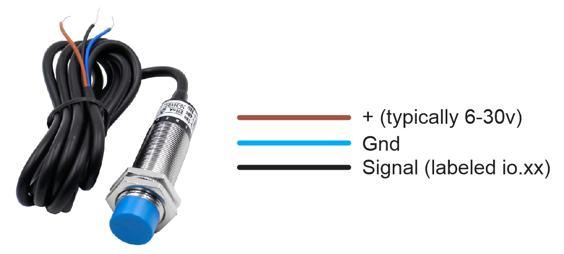
Example NPN proximity switch wiring.
Connect the brown wire to a voltage compatible with the sensor (typically 6-30v). You can use the voltage header in the middle of the controller. Connect the blue wire to any ground. Connect the black wire to Inputs labeled io.xx.
¶ Spindles
¶ PWM
The PWM output signals can be put on any of the 5V outputs.
¶ 0-10V
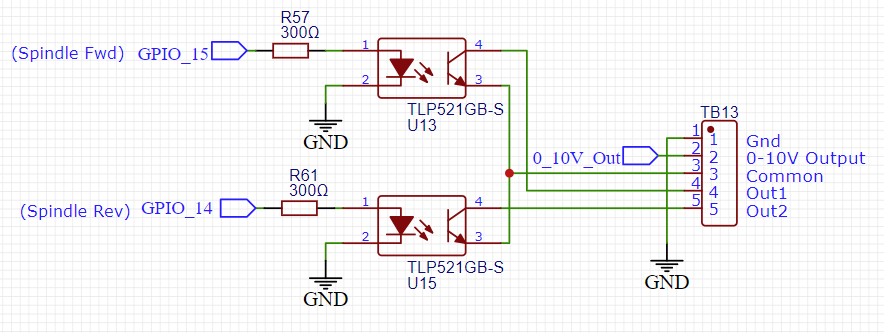
This uses an op-amp and a low pass filter to create an analog voltage. It can be adjusted with a trim pot for a max voltage of 5V to 10V. A good way to do this is to turn on the spindle to max RPM (gcode M3 S12000) or whatever your max is) and then adjust the pot until you get the desired max voltage. Do this before you connect to the spindle and measure the voltage between Gnd and the 0-10V output
The schematic for the forward and reverse connections looks like this. They are isolated from the ESP32 and connect Out1 and Out2 to a common ground on the VFD.
10V:
  forward_pin: gpio.15
  reverse_pin: NO_PIN
  pwm_hz: 5000
  output_pin: gpio.13
  enable_pin: gpio.14
  direction_pin: NO_PIN
  disable_with_s0: false
  s0_with_disable: true
  spinup_ms: 0
  spindown_ms: 0
  tool_num: 0
  speed_map: 0=0.000% 1000=0.000% 24000=100.000%
  off_on_alarm: false
¶ Laser
The laser can be put on any of the 5V outputs. If you also want to use have another spindle type. Set that one up first and see what I/O is left.
The laser power should wired directly to a power supply. It is not recommended to do it through the board via MOSFETs or other connections. Typically the controller power supply should have a shared ground.
¶ RS485
The RS485 circuit uses a MAX3485 chip. This requires the use a an rts_pin for data direction control.
There are LEDs to show and help debug communications issues.
- TX LED (labeled io15) You should see the TX blink a couple times per second. If you do not, something is wrong in your setup on the CNC controller side.
- Rx LED (labeled (RS485 Rx) The Rx should blink at the same rate (immediately after) as the Tx LED when communicating with the VFD. If the Rx LED stays on, try swapping the wires on the VFD side. If it does not light at all, there is probably a setup or other problem on the VFD side. Note: When no RS485 wires are connected the state of the LED is meaningless. Ignore that LED when not using RS485.
- RTS_LED (labeled i014) This should light the same time as the TX_LED.
Note: The circuit is a UART to RS485 converter. The LEDs represent the state of UART side IO. The idle state of a UART Tx is high, so the TX blinks are from on to off. The RTS LED will blink from off to on. It may be hard to see the Tx off blinks because the LED is bright and the off time is so brief. Try covering the other LEDs to see the blinks.
RS485 is a lot more complicated to setup than other types of spindles. It requires a lot of setup on the VFD side and good wiring. If you are having trouble, you should consider using the 0-10V method to control the spindle. It is very hard for us to support RS485 remotely.
Here is a typical RS485 config file section. This is specific to the 6x controller. You must also setup the VFD and get the wiring correct. For general information about VFD setup see the spindle wiki page.
For the my Huanyang, I connect the terminal labeled RS485 A on the controller to RS+ on the VFD and RS485 B on the controller to RS- on the VFD. I do not use the ground terminal.
# Begin Huanyang
uart1:
  txd_pin: gpio.15
  rxd_pin: gpio.16
  rts_pin: gpio.14
  baud: 9600
  mode: 8N1

Huanyang:
  uart_num: 1
  modbus_id: 1
  tool_num: 0
  speed_map: 0=0% 0=25% 6000=25% 24000=100%
  off_on_alarm: false
¶ MOSFETs
The (2) NPN MOSFETs are rated for 3A continuous and 5A peak. There are flyback diodes connected to VMot to make them safe for use with inductive loads, such as relays and solenoids.
The MOSFETs use gpio.4 and gpio.12. These I/O pins also activate 5V outputs.
The VMot terminals are always connected to VMot. Terminals labeled with the io pin numbers switch to ground when the io pins are active. If you need to operate devices with other voltages than VMot, you can use a separate DC power supply as long as it shares a common ground with the controller.
¶ Expansion Module Socket
The expansion module socket is designed for use with an I/O exapnsion module to give you more input, outputs and connections to displays and pendants. Some modules exist and some are under development and should be available in the future.
The socket is similar to the 6 pack modules except it only uses 2 I/O pins. You can partially use some 6 pack modules, but only the features that use the first 2 I/O pins. Examples: Relay module, 5V module (first 2 outputs only), Input module (first 2 inputs only).
You should only use modules that are designed for use with this controller. The socket pins connect directly to the ESP32 without any noise or ESD protection. The modules typically provide that protection. Directly wiring to the expansion socket will likely damage the controller.
You will need to provide a spacer to support the module. You can either use a 11mm long M3 threaded standoff or this 3D printed spacer (STL).
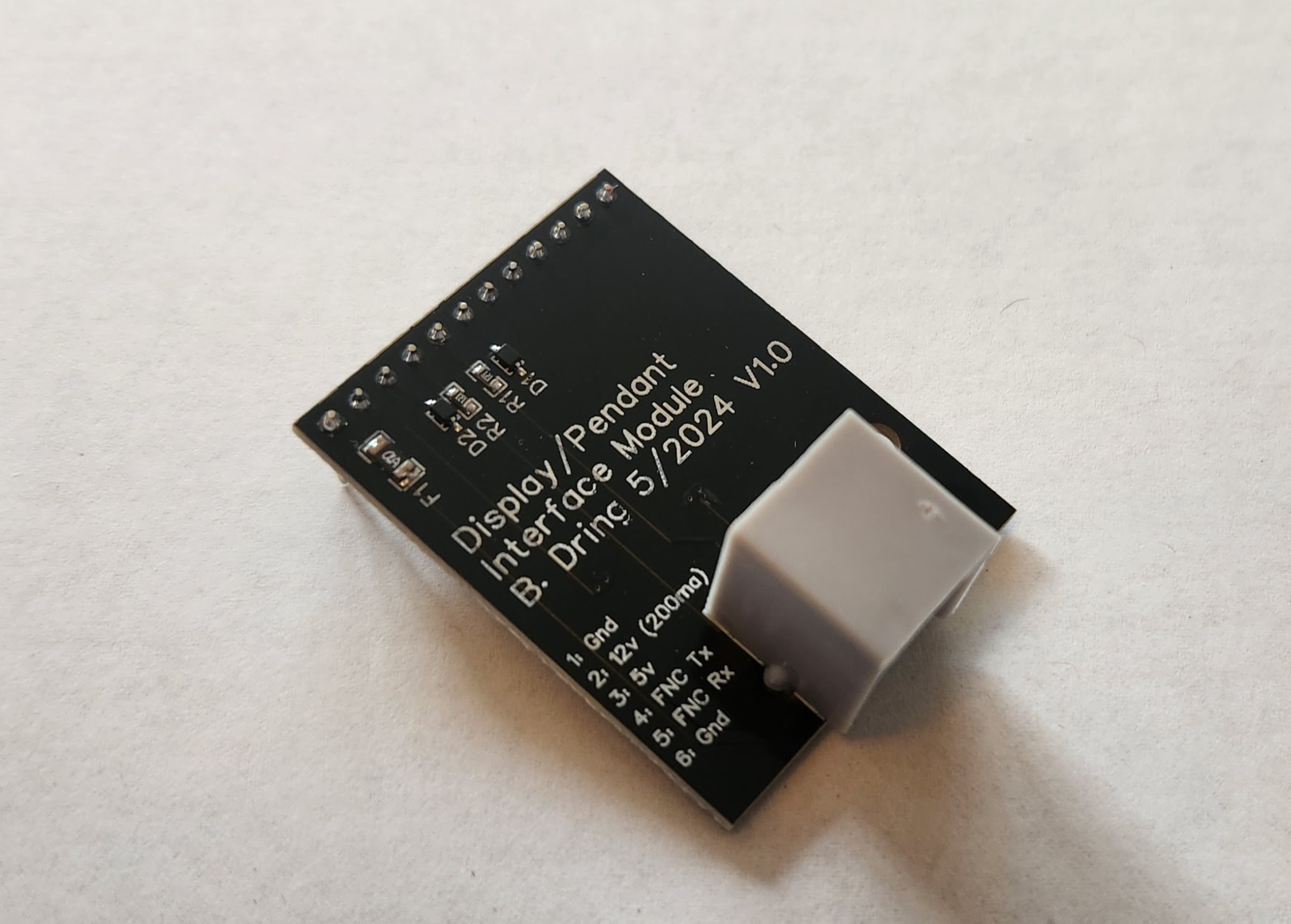
Here is a simple RJ12 module that can be used with the FluidDial
uart2:
  txd_pin: gpio.25
  rxd_pin: gpio.27
  rts_pin: NO_PIN
  cts_pin: NO_PIN
  baud: 1000000
  mode: 8N1

uart_channel1:
  report_interval_ms: 75
  uart_num: 2
¶ Outputs
¶ 5V Outputs
¶ Example Config File
name: "TMC2209 IO Test"
board: "FluidNC 4X 2209 V3"

stepping:
  engine: I2S_STATIC
  idle_ms: 255
  dir_delay_us: 1
  pulse_us: 4
  disable_delay_us: 0

# --- for TMC2209s -----
uart1:
  txd_pin: gpio.26
  rxd_pin: gpio.2
  baud: 115200
  mode: 8N1

axes:
  shared_stepper_disable_pin: NO_PIN

  x:
    steps_per_mm: 100
    max_rate_mm_per_min: 2000
    acceleration_mm_per_sec2: 100
    max_travel_mm: 1000
    homing:
      cycle: 3
      mpos_mm: 0
      positive_direction: false
      seek_mm_per_min: 1000
      feed_mm_per_min: 500

    motor0:
      limit_neg_pin: gpio.36:low
      limit_pos_pin: NO_PIN
      limit_all_pin: NO_PIN
      tmc_2209:
        uart_num: 1
        addr: 0
        r_sense_ohms: 0.110
        run_amps: 0.75
        hold_amps: 0.250
        microsteps: 4
        stallguard: 0
        stallguard_debug: false
        toff_disable: 0
        toff_stealthchop: 5
        toff_coolstep: 3
        run_mode: Stealthchop
        homing_mode: Stealthchop
        homing_amps: 0.50
        use_enable: false
        direction_pin: i2so.1
        step_pin: i2so.2
        disable_pin: i2so.0

  y:
    steps_per_mm: 100
    max_rate_mm_per_min: 2000
    acceleration_mm_per_sec2: 100
    max_travel_mm: 1000
    homing:
      cycle: 2
      mpos_mm: 0
      positive_direction: false
      seek_mm_per_min: 1000
      feed_mm_per_min: 500

    motor0:
      limit_neg_pin: gpio.39:low
      limit_pos_pin: gpio.33:low
      limit_all_pin: NO_PIN
      tmc_2209:
        uart_num: 1
        addr: 1
        r_sense_ohms: 0.110
        run_amps: 0.75
        hold_amps: 0.250
        microsteps: 4
        stallguard: 0
        stallguard_debug: false
        toff_disable: 0
        toff_stealthchop: 5
        toff_coolstep: 3
        run_mode: Stealthchop
        homing_mode: Stealthchop
        homing_amps: 0.50
        use_enable: false
        direction_pin: i2so.4
        step_pin: i2so.5
        disable_pin: i2so.7

    motor1:
      limit_neg_pin: NO_PIN
      limit_pos_pin: gpio.34:low
      limit_all_pin: NO_PIN
      tmc_2209:
        uart_num: 1
        addr: 2
        r_sense_ohms: 0.110
        run_amps: 0.75
        hold_amps: 0.250
        microsteps: 4
        stallguard: 0
        stallguard_debug: false
        toff_disable: 0
        toff_stealthchop: 5
        toff_coolstep: 3
        run_mode: Stealthchop
        homing_mode: Stealthchop
        homing_amps: 0.50
        use_enable: false
        direction_pin: i2so.9
        step_pin: i2so.10
        disable_pin: i2so.8

  z:
    steps_per_mm: 100
    max_rate_mm_per_min: 2000
    acceleration_mm_per_sec2: 100
    max_travel_mm: 1000
    homing:
      cycle: 1
      mpos_mm: 0
      positive_direction: true
      seek_mm_per_min: 1000
      feed_mm_per_min: 500

    motor0:
      limit_neg_pin: NO_PIN
      limit_pos_pin: gpio.35:low
      limit_all_pin: NO_PIN
      tmc_2209:
        uart_num: 1
        addr: 3
        r_sense_ohms: 0.110
        run_amps: 0.75
        hold_amps: 0.250
        microsteps: 4
        stallguard: 0
        stallguard_debug: false
        toff_disable: 0
        toff_stealthchop: 5
        toff_coolstep: 3
        run_mode: Stealthchop
        homing_mode: Stealthchop
        homing_amps: 0.50
        use_enable: false
        direction_pin: i2so.12
        step_pin: i2so.13
        disable_pin: i2so.15

spi:
  miso_pin: gpio.19
  mosi_pin: gpio.23
  sck_pin: gpio.18

i2so:
  bck_pin: gpio.22
  data_pin: gpio.21
  ws_pin: gpio.17

sdcard:
  cs_pin: gpio.5
  card_detect_pin: NO_PIN

coolant:
  flood_pin: gpio.12
  mist_pin: gpio.4
  delay_ms: 0

user_outputs:
  digital0_pin: gpio.15
  digital1_pin: gpio.14
  digital2_pin: gpio.13

probe:
  pin: gpio.32:low

# 10V:
  # forward_pin: gpio.15
  # reverse_pin: NO_PIN
  # pwm_hz: 5000
  # output_pin: gpio.13
  # enable_pin: gpio.14
  # direction_pin: NO_PIN
  # disable_with_s0: false
  # s0_with_disable: true
  # spinup_ms: 0
  # spindown_ms: 0
  # tool_num: 0
  # speed_map: 0=0.000% 1000=0.000% 24000=100.000%
  # off_on_alarm: false

# ==== Begin RS485 Be sure pendant is not using UART 2 ===
#uart2:
#  txd_pin: gpio.15
#  rxd_pin: gpio.16
#  rts_pin: gpio.14
#  baud: 9600
#  mode: 8N1

#Huanyang:
#  uart_num: 2
#  modbus_id: 1
#  tool_num: 0
#  speed_map: 0=0% 0=25% 6000=25% 24000=100%
#  off_on_alarm: false

# ==== End RS485 ===

start:
  must_home: false
  deactivate_parking: false
  check_limits: false
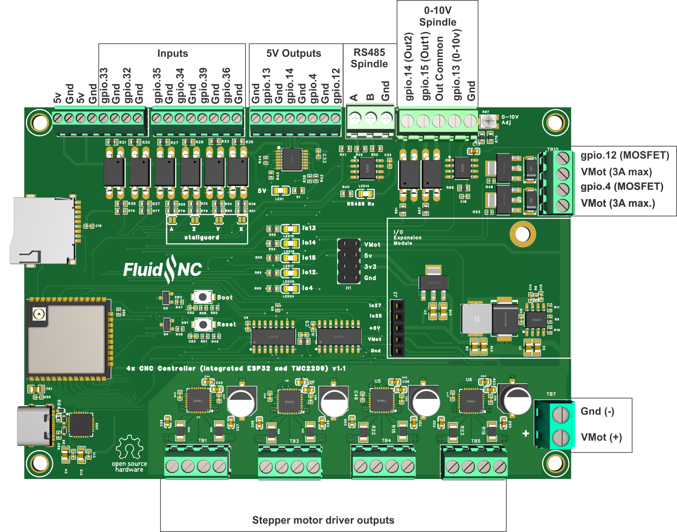
¶ Pinout Diagram
Note: The silkscreen on the back of the v1.1 controller is incorrect for the v1.1 controllers. Use this diagram.
You may notice GPIO.13 and GPIO.14 reversed orientation wise.
¶ Documentation
- Open souce design files at OSHW Labs
- 3D model at GrabCAD
- STLs for a case at Printables